Hopper type mucking loader for narrow-roadway mine shaft

A narrow roadway and slag removal machine technology, applied in the field of mining machinery, can solve the problems of low ore conveying efficiency, long machine length, belt wear, etc., to facilitate observation of the work site, reduce the length of the machine, and prolong the service life Effect

Active Publication Date: 2015-09-02
烟台智联科创矿山设备有限公司
View PDF7 Cites 3 Cited by
  • Summary
  • Abstract
  • Description
  • Claims
  • Application Information

AI Technical Summary

Problems solved by technology

However, because the slag removal machine transports the ore to a high place and then fills it, the belt conveyor is arranged obliquely, and the ore often slides down during the conveying process, which results in low ore conveying efficiency and serious belt wear
At the same time, because the conveying device needs to be arranged obliquely, the end of the conveying device needs to reach a certain height, and the inclination angle between the conveying device and the ground should not be too large, so the length of the conveying device is longer, and the length of the whole machine is also longer , it is not flexible to work underground
[0005] At present, the human-machine relationship of the slag scraper is not very harmonious. The specific performance is that the operation table of the slag scraper is fixed on the equipment. However, due to the small space in the mine, the operator's vision is affected, and the operability of the equipment is not good.
In addition, the operator station is fixed to the equipment, and the operator must sit on the equipment, restricting the operator to an uncomfortable working environment

Method used


Image

  • Hopper type mucking loader for narrow-roadway mine shaft
  • Hopper type mucking loader for narrow-roadway mine shaft
  • Hopper type mucking loader for narrow-roadway mine shaft

Examples


Embodiment Construction

[0027] The present invention will be further described below in conjunction with specific embodiments, and the advantages and characteristics of the present invention will become clearer along with the description. However, these embodiments are only exemplary and do not constitute any limitation to the scope of the present invention. Those skilled in the art should understand that the details and forms of the technical solutions of the present invention can be modified or replaced without departing from the spirit and scope of the present invention, but these modifications and replacements all fall within the protection scope of the present invention.

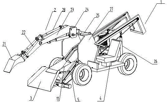
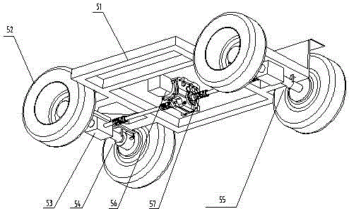
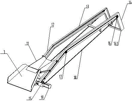
[0028] see Figure 1 to Figure 5 , the present invention relates to a hopper-type slag removal machine for narrow tunnel mines, including a traveling chassis 5, a cab 4 installed on the traveling chassis 5, an ore conveying device 1, a retractable shovel mouth 3, a control unit and a working device 2. The front end of ...


PUM


Abstract

The invention relates to a hopper type mucking loader for a narrow-roadway mine shaft. The hopper type mucking loader comprises a traveling chassis, a cab, an ore conveying device, a retractable shovel opening, a control unit and a working device, wherein the cab, the ore conveying device, the retractable shovel opening, the control unit and the working device are mounted on the traveling chassis. The front end of the ore conveying device and a frame of the traveling chassis are hinged together, the rear end of the ore conveying device is supported by two synchronously-telescoping hydraulic cylinders, the retractable shovel opening is mounted at the front end of the ore conveying device, the working device is positioned on the frame of the traveling chassis, the control unit is mounted in the cab, the input end of the control unit is connected with a handheld operation handle, and the traveling chassis, the ore conveying device, the retractable shovel opening and the working device are connected with the output end of the control unit. The hopper type mucking loader for the narrow-roadway mine shaft has the advantages that ore conveying efficiency is improved, service life of the mucking loader is prolonged, traveling and position transferring of the mucking loader in a narrow roadway are facilitated, an operator can observe working sites conveniently, and the cab can be distant from the mucking loader, so that working comfort level is improved.

Description

technical field [0001] The invention belongs to the field of mining machinery, and more specifically relates to an ore loading device. Background technique [0002] Most of the slag removal machines in mines at the present stage are designed for large mines, but for mines with narrow lanes, such slag removal machines are heavy and not flexible enough to work, requiring multiple staff to operate. On-site investigation found that one driver (operator) is needed for a slag removal machine in the mine. In addition, because the ore will be stuck or difficult to load during the loading process, the driver of the slag removal machine cannot take care of the situation in front of the vehicle or The situation behind the car, so at this stage, the slag scraper needs at least 3~4 staff to assist in the operation. [0003] Due to the high humidity in the mine and the temperature basically in the range of 20-25°C, the working life of the current slag removal machine is not long, and i...

Claims


Application Information

Patent Timeline
Patent Type & Authority Applications(China)
IPC IPC(8): E02F3/34E02F7/02E21C35/20
Inventor 吕怀江
Owner 烟台智联科创矿山设备有限公司
Why Eureka
Try Eureka