
A two-speed drive wheel

A transmission wheel and transmission shaft technology, which is applied to transmission elements, transmission parts, multi-ratio transmissions, etc., can solve problems such as difficult to achieve coaxial input and output, large component layout, and short service life of gears. Achieve the effect of solving the problem of bearing installation, simple structure and long service life

Active Publication Date: 2017-08-11
管继尧
View PDF5 Cites 0 Cited by
  • Summary
  • Abstract
  • Description
  • Claims
  • Application Information

AI Technical Summary

Problems solved by technology

[0002] At present, there are many transmission devices with variable speed functions, such as gearboxes and gear transmission components that transmit power through the transmission gear train. The purpose of shaft input and output, and its noise is large, power consumption is large, and the service life of its gears is not long
[0003] For example, in the production process of the rice huller, the diameter of the valley roller becomes smaller due to friction, so after the rice huller has been working for a period of time, the speed of the transmission to the valley roller needs to be adjusted properly, otherwise there will be broken rice or the broken rate will not be correct. In advanced cases, the general solution is to use a gearbox for speed change and transmission, resulting in high manufacturing costs, difficult maintenance and maintenance, and the layout of components takes up a lot of space

Method used


Image

  • A two-speed drive wheel
  • A two-speed drive wheel
  • A two-speed drive wheel

Examples


Embodiment Construction

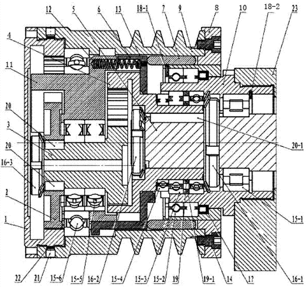
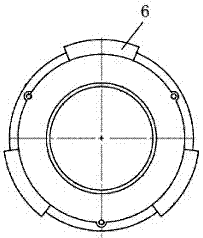
[0023] Such as figure 1 to Figure 7 As shown, the present embodiment includes: the end cover internal gear is the first internal gear 1; the speed change external gear is the first external gear 2; the speed change pinion is the second external gear 3; the output internal gear is the second internal gear 4; Shaft 5; two-way three-jaw mobile clutch also called multi-claw clutch block 6; movable ejector rod 7; concave-convex speed-regulating plate 8; transmission wheel 9; fixed bearing seat 10; eccentric balance bearing seat 11; clutch spring is elastic Part 12; Spring positioning pin 13; Positioning screw pin 14; Bearing 15-1, 15-2, 15-3, 15-4, 15-5, 15-6; Locking round nut and stop washer 16-1, 16-2, 16-3; Skeleton oil seal 17; Elastic bearing rings 18-1, 18-2 for holes; Bearing bushings 19, 19-1; Flat keys 20, 20-1; ; Copper pad 22 ;

[0024] Transmission wheel 9, used for input or output speed;

[0025] Gear set, used for transmission wheel speed change;

[0026] The...


PUM


Abstract

The invention discloses a double-speed driving wheel. The double-speed driving wheel comprises the driving wheel, a gear set, a balancing bearing seat, a clutch and a transmission shaft. The driving wheel is used for inputting or outputting a rotating speed. The gear set is used for speed changing of the driving wheel. The balancing bearing seat is used for positioning of the gear set, and a weight center line after being counterbalanced with the gear set is coincided with a geometric center line of the driving wheel at the same time; the clutch is used for the separation and reunion between the driving wheel and the output shaft. The transmission shaft is used for inputting or outputting the rotating speed. The gear set, the balancing bearing seat, the clutch and the transmission shaft are all located in a cylinder formed by the driving wheel. The driving wheel and the output shaft possess a same axis. According to the double-speed driving wheel, two different kinds of rotating speeds can be output coaxially in a same direction, the gear set and the clutch are arranged in the driving wheel, the balancing bearing seat is matched, the problems of balance and bearing installation are solved, and the massive structure is small and exquisite. The double-speed driving wheel applies to a plurality of speed changing occasions, especially to the speed changing of a rice huller.

Description

technical field [0001] The invention relates to a transmission device, especially a coaxial two-speed output transmission wheel with a built-in clutch and a transmission. Background technique [0002] At present, there are many transmission devices with variable speed functions, such as gearboxes and gear transmission components that transmit power through the transmission gear train. The purpose of shaft input and output, and its noise is large, power consumption is large, and the service life of its gear is not long. [0003] For example, in the production process of the rice huller, the diameter of the valley roller becomes smaller due to friction, so after the rice huller has been working for a period of time, the speed of the transmission to the valley roller needs to be adjusted properly, otherwise there will be broken rice or the broken rate will not be correct. In advanced cases, the general solution is to use a gearbox for speed change and transmission, resulting i...

Claims


Application Information

Patent Timeline
Patent Type & Authority Patents(China)
IPC IPC(8): F16H57/023
CPCF16H57/023F16H2200/0004
Inventor 管继尧
Owner 管继尧
Learn More