New-energy electric connection system

A technology of power connection and new energy, applied in the direction of connection, two-part connection device, circuit, etc., can solve the problems that electric energy cannot be stored and cannot be automatically converted, and achieves the effects of easy maintenance, low construction cost, and reduced labor intensity

Active Publication Date: 2015-09-02
南通浦舆电子科技有限公司
View PDF5 Cites 11 Cited by
  • Summary
  • Abstract
  • Description
  • Claims
  • Application Information

AI Technical Summary

Problems solved by technology

[0003] The Chinese patent application number 201410170743.3 discloses a smart home power connection system, which includes a power connection guide rail and a socket board module. There are slots on the top surface of the power connection guide rail, and conductive copper wires are placed in the slots, and inserted into the slots. The socket board module electrically connects the wires to the socket board module. Although the connection system replaces the traditional pre-buried wall wiring method by rationally modifying the wiring form, it simplifies the complexity of decoration and increases the convenience of installation. However, this power connection system is in There is no automatic conversion between the power storage module and the power consumption module, resulting in the inability to store electric energy

Method used


Image

  • New-energy electric connection system
  • New-energy electric connection system
  • New-energy electric connection system

Examples


Embodiment

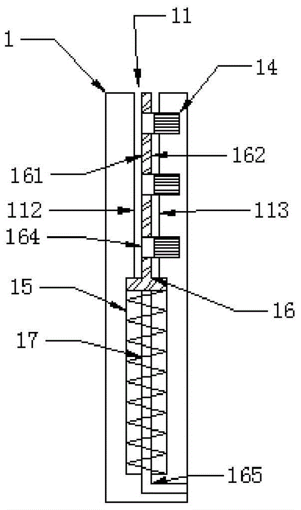
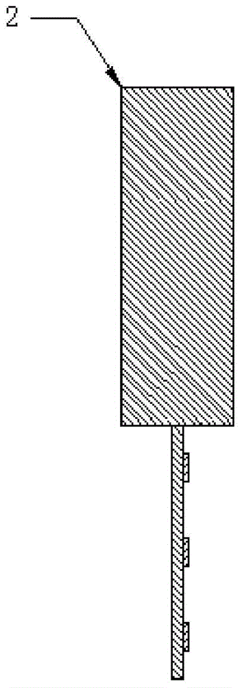
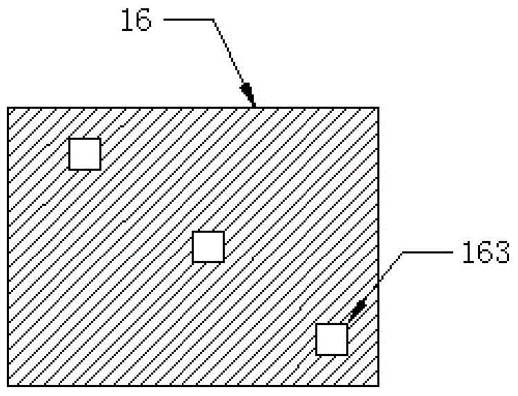
[0027] A new energy power connection system, including a power connection guide rail 1 and a socket board module 2, the structures of which are as follows figure 1 and figure 2 As shown, the opening on the top surface of the power connection guide rail 1 is provided with a power module slot 11; the power module slot 11 has an insulating surface 112 and a wiring surface 113; Bar 14, the conductive copper strip 14 is respectively connected with the zero wire, the ground wire and the live wire of the power supply; the slot bottom of the electrical module slot 11 is provided with a conversion panel installation groove 15; several conversion panels are installed in the conversion panel installation groove 15 16. The structure of the conversion panel 16 is as Figure 3-4 As shown, the width of each conversion panel along the direction of the guide rail is equal to the width of the socket board module 2, and springs 17 are respectively arranged between each conversion panel 16 and ...


PUM


Abstract

The invention relates to a new-energy electric connection system, and the system comprises an electric connection guide rail and a matched socket board module. The top opening of the electric connection guide rail is provided with an electric module slot, and two sides of the electric connection guide rail are respectively provided with an insulation surface and a wiring surface. The wiring surface is sequentially provided with conductive copper bars from the top to the bottom, wherein the conductive copper bars are respectively connected with the zero line, ground line and live wire of a power supply. The system also comprises a switch panel installation slot, a spring and a power storage interface, and a switch panel is pushed into the electric module slot under the action of the spring to contact with the conductive copper bars, or is pressed back into the panel installation slot to contact with the power storage interface, so as to achieve power conversion between the power storage module and the power supply. The system enables a power system to achieve automatic conversion between the power storage module and the electric module, can be used in a residential building or an office building more safely and conveniently so as to replace a conventional buried type electric connection system.

Description

technical field [0001] The invention relates to a power connection system, in particular to a new energy power connection system. Background technique [0002] Smart home is based on the residence as a platform, using integrated wiring technology, network communication technology, security technology, automatic control technology, audio and video technology to integrate home life-related facilities to build an efficient management system for residential facilities and family schedules. Smart home electrical system products can be said to be the most basic products in smart home. Other smart home systems need to complete power transmission and wiring management based on smart home electrical systems. Therefore, research and development of convenient and safe power connection systems have become One of the technical problems to be solved urgently. [0003] The Chinese patent application number 201410170743.3 discloses a smart home power connection system, which includes a pow...

Claims


Application Information

Patent Timeline
Patent Type & Authority Applications(China)
IPC IPC(8): H01R29/00H01R25/14H01R24/00H01R13/46
CPCH01R13/46H01R24/00H01R25/142H01R25/145H01R29/00
Inventor 朱文廷耿恩华吴国欣罗楠
Owner 南通浦舆电子科技有限公司
Why Eureka
Try Eureka