Asynchronous motor parameter offline identification method

A technology for asynchronous motors and identification methods, which is applied in the direction of AC motor control, electrical components, control systems, etc., can solve the problems of low identification accuracy, complicated operation process, and error of identification results, and achieve high identification accuracy, simple identification method, The effect of small identification error

Active Publication Date: 2015-09-02
ZHUZHOU NAT ENG RES CENT OF CONVERTERS
View PDF5 Cites 18 Cited by
  • Summary
  • Abstract
  • Description
  • Claims
  • Application Information

AI Technical Summary

Problems solved by technology

A simple method commonly used for stator resistance identification is to measure by DC voltammetry, but in this method, the dead zone of the inverter and the skin effect have a great influence on the accuracy of the reconstructed voltage under low voltage conditions , and the possible measurement error of each data point
In order to reduce the measurement error, the two-point method, the method of calculating the average value of multiple measurements, or the voltage compensation method are mainly used at present, but the measurement data points of the two-point method are limited, and the measurement error cannot be effectively reduced; multiple measurements are averaged The operation process of the value method is complicated, and multiple identification operations are required, and even the inverter needs to be started multiple times. Since the data points with large errors and wrong data points in the measurement cannot be ruled out, the identification results in practical applications There are large errors, and the identification accuracy is not high; the voltage compensation method requires voltage compensation, the identification process and algorithm are complex, and the requirements for the sampling device and processor of the system are high, which is not conducive to practical application

Method used


Image

  • Asynchronous motor parameter offline identification method
  • Asynchronous motor parameter offline identification method
  • Asynchronous motor parameter offline identification method

Examples


Embodiment Construction

[0047] The present invention will be further described below in conjunction with the accompanying drawings and specific preferred embodiments, but the protection scope of the present invention is not limited thereby.

[0048] In this embodiment, the asynchronous motor is in a static state, and the wiring mode of the inverter output to the motor remains unchanged. In the data analysis process, the voltage reconstructed by the modulation voltage of the inverter for control is used. The modulation voltage of the inverter is based on the DC voltage The reconstructed voltage does not need to consider the skin effect and dead zone compensation, and does not require an additional voltage sampling device or equipment to collect voltage from the inverter; in addition, the inverter output current is sampled using the built-in inverter The current sampling of at least one phase is realized, and there is no need to add additional current sampling equipment to collect current.
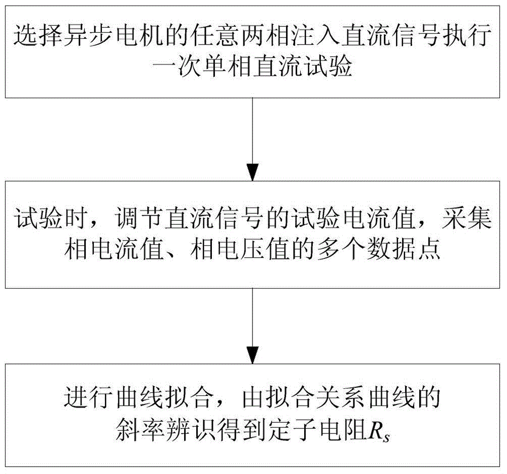
[0049] 1. ...


PUM


Abstract

The invention discloses an asynchronous motor parameter offline identification method comprising a stator resistor identification step including selecting two random phases of an asynchronous motor to serve as two tested phases, injecting a DC signal to windings of the two tested phases, and executing a one-time single phase DC test; the method also comprises the following steps: adjusting a test current value of the injected DC signal, collecting a phase current value and a corresponding phase voltage value of one tested phase at different test current values, thus obtaining a plurality of data points formed by phase current values and phase voltage values; carrying out curve fitting according to the collected data points so as to obtain a fitting relation curve between the phase current value and the phase voltage value, thus identifying a stator resistance Rs value according to a gradient of the fitting relation curve. The asynchronous motor parameter offline identification method is simple in identification process, high in identification result precision, and small in identification error.

Description

technical field [0001] The invention relates to the technical field of asynchronous motor parameter identification, in particular to an off-line identification method for asynchronous motor parameters. Background technique [0002] In the high-performance control mode of asynchronous motors (such as speed sensorless vector control), it is necessary to know the motor parameters such as stator and rotor resistance, leakage inductance and mutual inductance of the motor. The above motor parameters are generally only provided by the motor manufacturer, and these parameters are not directly provided when the motor leaves the factory, but need to be obtained from the motor manufacturer separately. Therefore, it is difficult to directly obtain the motor parameters in practice. For example, for some renovation projects, the motor may It is an old motor, and it is no longer possible to obtain relevant motor parameters directly from the manufacturer. The relevant technology of motor p...

Claims


Application Information

Patent Timeline
Patent Type & Authority Applications(China)
IPC IPC(8): H02P25/00H02P27/06
Inventor 曹洋彭勃秦灿华吴强罗仁俊黄欢肖伟李嘉张志陈孟君唐建宇林丽仇乐兵徐万良梁文超刘永丰黄迪刘永丽何伟
Owner ZHUZHOU NAT ENG RES CENT OF CONVERTERS
Why Eureka
Try Eureka