led linear constant current drive circuit

A linear constant current drive, linear constant current technology, applied in the direction of lamp circuit layout, electric light source, lighting devices, etc., can solve the problems of reducing power factor, low efficiency, etc., to improve efficiency and power factor, improve efficiency, and ensure power Factor effect

Active Publication Date: 2017-06-16
SILERGY SEMICON TECH (HANGZHOU) CO LTD
View PDF4 Cites 1 Cited by
  • Summary
  • Abstract
  • Description
  • Claims
  • Application Information

AI Technical Summary

Problems solved by technology

[0004] In view of this, the object of the present invention is to provide a LED linear constant current drive circuit to solve the technical problems in the prior art that the efficiency is low and the power factor will be reduced by increasing the efficiency

Method used


Image

  • led linear constant current drive circuit
  • led linear constant current drive circuit
  • led linear constant current drive circuit

Examples


Embodiment 1

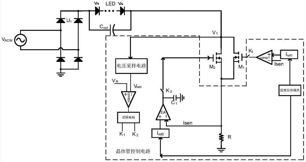
[0025] Embodiment 1: Reference figure 1 As shown, an embodiment of the present invention is illustrated, including a rectifier circuit U 1 and linear constant current control circuit, the input voltage V ACIN After the rectification circuit U 1 After rectification, it is input to the LED load, and the output capacitor C is connected in parallel with the LED load. out . The linear constant current control circuit is connected in series with the negative terminal of the LED load, and the linear constant current control circuit controls the average current flowing through the LED load to keep constant; at the same time, the other end of the linear constant current control circuit is connected to a resistor R, and the resistance R The other end is grounded.

[0026] The linear constant current control circuit includes a power transistor circuit and a transistor control circuit. In this embodiment, the power transistor circuit includes two parallel power transistors, respective...

Embodiment 2

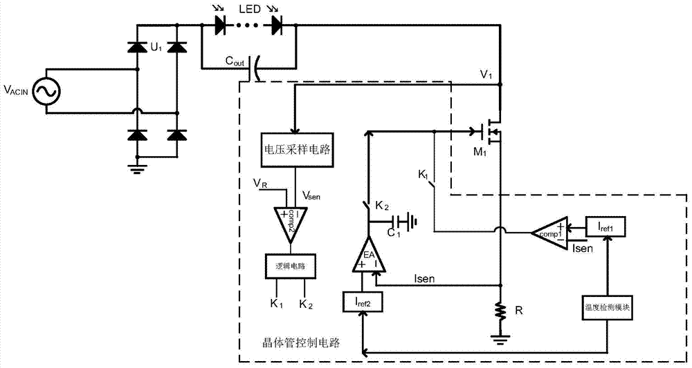
[0029] Embodiment two: reference figure 2As shown, another specific implementation manner of the present invention is illustrated. For the same parts as in the first embodiment, refer to the first embodiment, and details are not repeated here. The difference between this embodiment and the first embodiment is that two power transistors are replaced by one transistor, and according to the sampling voltage signal V sen with V R (characterized by preset reference voltage V ref ) to determine which working range to work in. If V sen greater than V R is located in the second working interval T 2 , then the comparator COMP 1 The output terminal of the power transistor M 1 The control terminal is connected, if V sen less than V R is located in the first working interval T 1 and the third working interval T 3 , then the error amplifier EA 1 The output terminal (and there is a capacitor C at the output terminal 1 for error compensation) with the power transistor M 1 The ...

Embodiment 3

[0031] Embodiment three: reference image 3 As shown, an implementation mode of introducing voltage feedforward is illustrated. It can be seen from the figure that it is a further improvement scheme based on the second embodiment. In fact, introducing the voltage feedforward into the first embodiment can also be realized. Take the improvement of Example 2 as an example. Mainly the sampling voltage signal V sen Transformed into a feed-forward voltage signal V with the opposite trend F , using the feed-forward voltage signal as the first current reference value I ref1 .

[0032] For how to sample the voltage signal V sen transformed into a feed-forward voltage signal V F There are many implementations, so here is only an example: subtract the sampled voltage signal V from a constant voltage signal sen , the constant voltage signal can be optionally greater than the sampling voltage signal V sen peak signal.


PUM


Abstract

The invention discloses an LED linear constant current drive circuit. The invention can form a first working interval, a second working interval and a third working interval in one power frequency cycle, and the current in the first working interval and the third working interval is greater than In the second working area, a current curve with small two ends is formed in the middle, and the average current value is kept unchanged to realize linear constant current drive control. This solution can improve the efficiency of the linear constant current drive, and also ensure the power factor. At the same time, a temperature feedback is set to control the temperature rise, and the voltage feedforward is introduced as a reference value, which can further improve the efficiency and power factor.

Description

technical field [0001] The invention relates to the technical field of power electronics, in particular to an LED linear constant current drive circuit. Background technique [0002] Most of the LED driving circuits in the prior art are switching power supply types, and the flyback switching power supply is the main type, generally including a rectifying circuit, a power stage circuit and a control circuit. Input to the power stage circuit, the power stage circuit performs voltage conversion, and the control circuit is used to control the on-off of the main power switch tube in the power stage circuit, so as to realize constant current drive. In the prior art above, the power stage circuit of the flyback switching power supply includes a transformer composed of primary and secondary sides, and the transformer occupies a relatively large volume and is expensive to implement. [0003] In the prior art, besides the above switching power supply type LED driving circuit, there i...

Claims


Application Information

Patent Timeline
Patent Type & Authority Patents(China)
IPC IPC(8): H05B37/02
Inventor 黄晓冬刘国家赵晨黄秋凯
Owner SILERGY SEMICON TECH (HANGZHOU) CO LTD
Why Eureka
Try Eureka