Drive protection circuit, semiconductor module, and automobile

一种驱动保护电路、驱动电路的技术,应用在紧急保护电路装置、电动汽车、自动断开的紧急保护装置等方向,能够解决无法抑制不良影响等问题,达到抑制浪涌电压的效果

Active Publication Date: 2015-09-02
MITSUBISHI ELECTRIC CORP
View PDF9 Cites 10 Cited by
  • Summary
  • Abstract
  • Description
  • Claims
  • Application Information

AI Technical Summary

Problems solved by technology

As a result, there is a problem that sometimes the adverse effect of the surge voltage on the switching element cannot be suppressed.

Method used


Image

  • Drive protection circuit, semiconductor module, and automobile
  • Drive protection circuit, semiconductor module, and automobile
  • Drive protection circuit, semiconductor module, and automobile

Examples


Embodiment approach 1

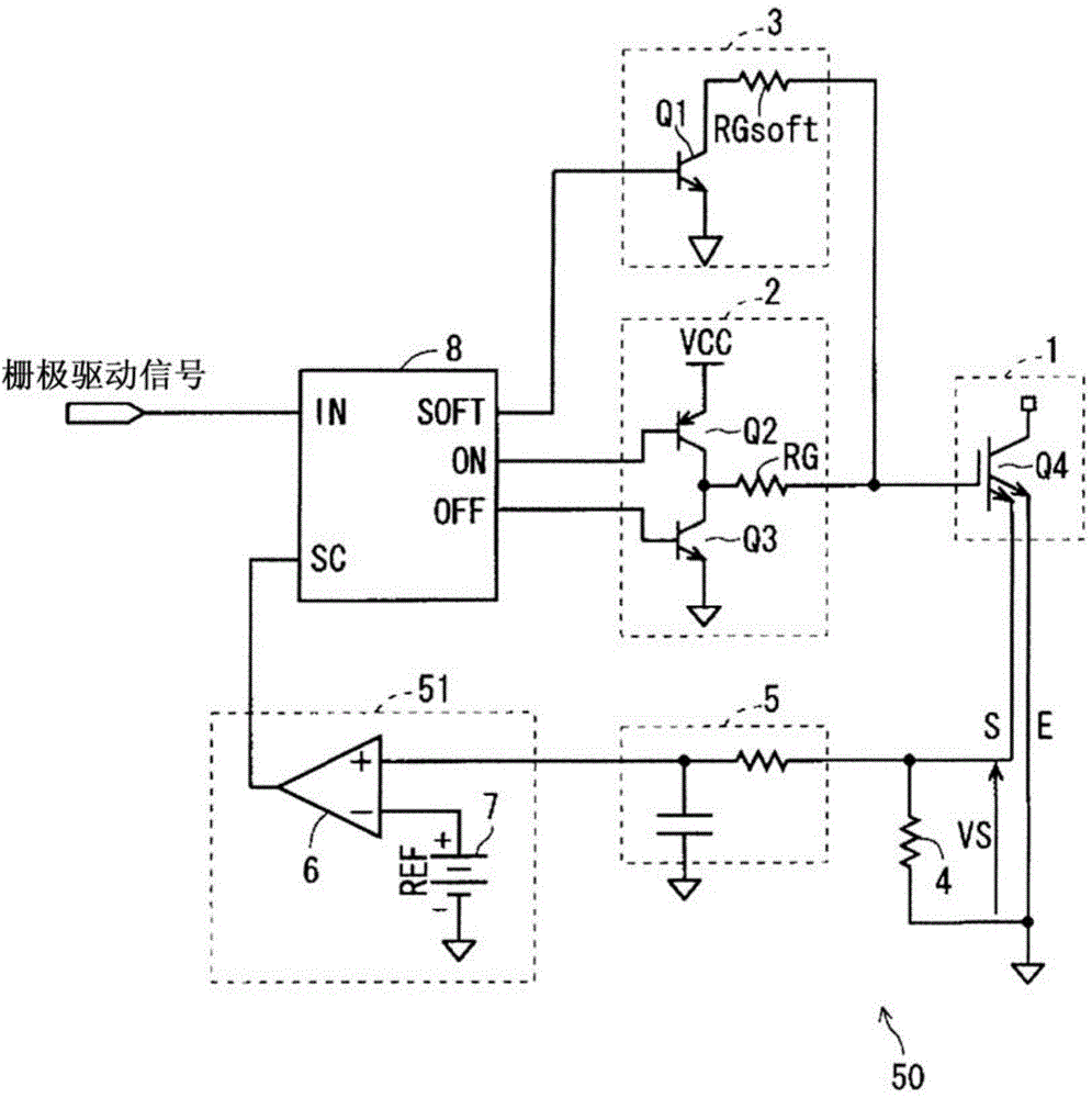
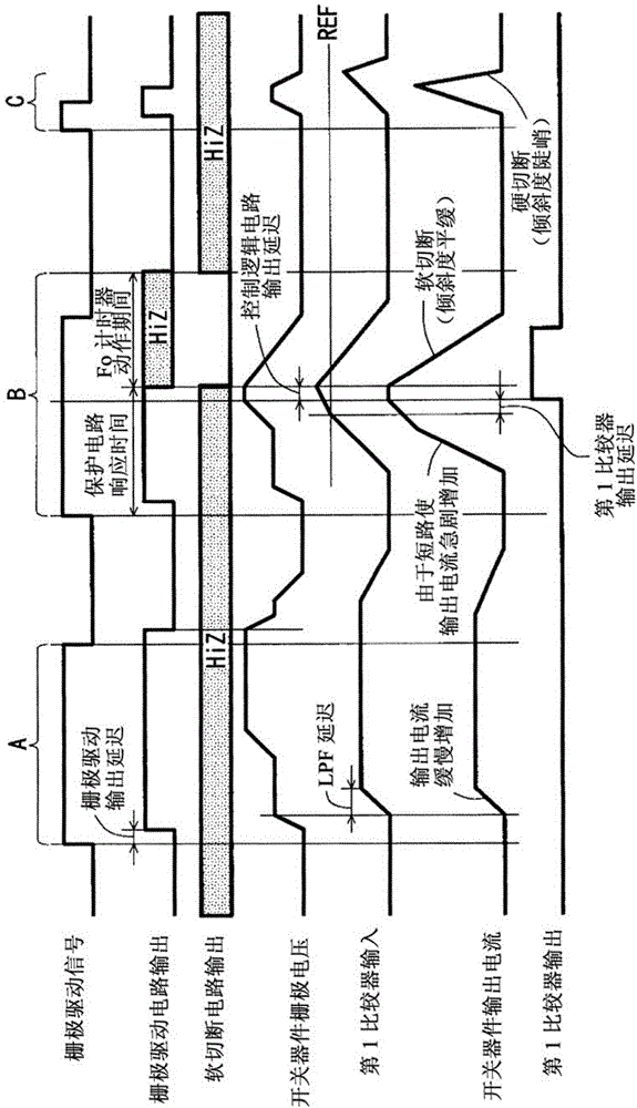
[0033] First, before describing the drive protection circuit according to Embodiment 1 of the present invention, a drive protection circuit related thereto (hereinafter referred to as "related drive protection circuit") will be described. figure 1 is a circuit diagram showing the structure of the relevant drive protection circuit, figure 2 It is a diagram showing the operation timing of the relevant drive protection circuit.

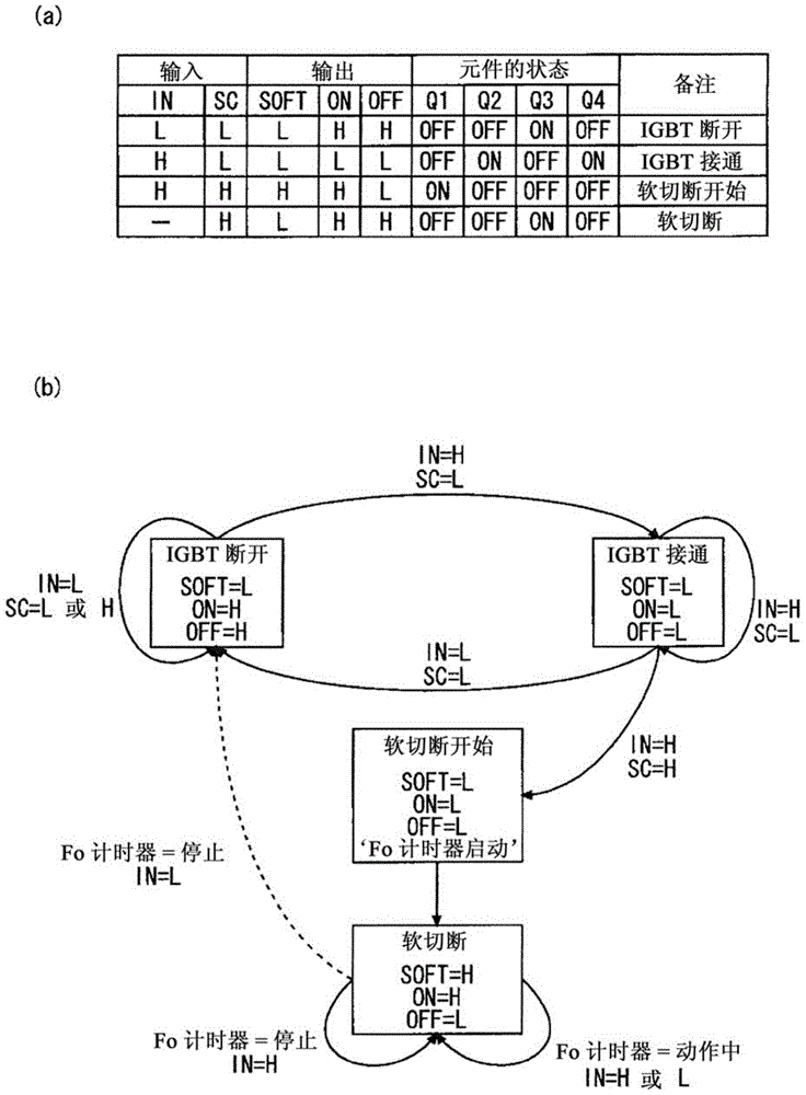
[0034] The relevant driving protection circuit is a circuit for driving and protecting the switching element Q4 of the switching device 1, such as figure 1 As shown, the relevant drive protection circuit is composed of the following components: gate drive circuit (drive circuit) 2, soft cut-off circuit 3, sense resistor 4, low-pass filter (LPF) 5, first comparator 6, with A power source 7 for the reference voltage REF, and a control logic circuit 8 for collectively controlling them.

[0035] Among these structural elements, the structural elements oth...

Embodiment approach 2

[0103] Figure 14 It is a circuit diagram showing the configuration of the drive protection circuit according to Embodiment 2 of the present invention, Figure 15 It is a figure which shows the operation timing of this drive protection circuit. In addition, in the drive protection circuit according to the second embodiment, the same or similar components as those described in the first embodiment are denoted by the same reference numerals, and the following description will focus on the differences.

[0104] The drive protection circuit according to Embodiment 2 is Figure 8 In the drive protection circuit according to Embodiment 1 shown, a third comparator 16 and a power supply 17 having a reference voltage Vmirror are provided instead of the timer circuit 11 .

[0105] In the drive protection circuit according to the second embodiment configured as described above, the mirror period of the switching element Q4 is used instead of the response time of the above-described ove...

Embodiment approach 3

[0113] Figure 18 It is a circuit diagram showing the configuration of the drive protection circuit according to Embodiment 3 of the present invention, Figure 19 It is a figure which shows the operation timing of this drive protection circuit. In addition, in the drive protection circuit according to Embodiment 3, the same or similar constituent elements as those described in Embodiment 1 are assigned the same reference numerals, and the following description will focus on differences.

[0114] The drive protection circuit according to Embodiment 3 is Figure 8 In the drive protection circuit according to Embodiment 1 shown, the gate voltage of the switching element Q4 is input to the timer circuit 11 instead of the gate drive signal.

[0115] In the driving protection circuit according to the third embodiment configured as described above, instead of the above-mentioned ON pulse width of the gate driving signal, the pulse width from the rise of the gate voltage of the swit...


PUM


Abstract

The purpose of the present invention is to provide a technology capable of reliably suppressing surge voltage, even if noise having a small pulse width is generated. The drive protection circuit drives and protects a switching element (Q4) and comprises: a gate drive circuit (2) that drives the switching element in response to a gate drive signal; and an overcurrent protection circuit (50) that operates a soft isolation circuit (3) that transitions the switching element (Q4) from ON to OFF at a slower switching speed than the gate drive circuit (2), when the switching element (Q4) has an overcurrent. The drive protection circuit transitions the switching element (Q4) from ON to OFF by using the soft isolation circuit (3) regardless of overcurrent, if the pulse width when the gate drive signal is ON is no greater than the response time for the overcurrent protection circuit (50).

Description

technical field [0001] The present invention relates to a drive protection circuit for driving and protecting a switching element such as a voltage-controlled semiconductor switching element of a power module, a semiconductor module, and an automobile. Background technique [0002] It is known that, in a switching circuit composed of semiconductor switching elements such as MOSFETs, IGBTs, and SiC MOSFETs, due to overload or short-circuiting the load (for example, turning on both the high-voltage (High) side and the low-voltage (Low) side at the same time, When the output current of the semiconductor switching element is too large due to an abnormality such as a short circuit of the bridge arm of the semiconductor switching element, if the switching element is turned off at a fast switching speed, a surge voltage that adversely affects the switching element will occur. [0003] Therefore, it has been proposed that, in the above-mentioned switching circuit, when the output cu...

Claims


Application Information

Patent Timeline
Patent Type & Authority Applications(China)
IPC IPC(8): H02H7/122H02H3/08H02P27/06
CPCH03K17/166H03K17/168H03K17/0828H02M1/08H02M1/32Y02T10/70H02H3/093
Inventor 日山一明
Owner MITSUBISHI ELECTRIC CORP
Why Eureka
Try Eureka