
Cone sand making machine two-component rolling sand making cavity assembly and production method thereof

A conical sand making machine, two-component technology, applied in the direction of grain processing, etc., can solve the problems of small wear state, scrapping of the wall of the rolling mortar, and serious wear, so as to prolong the service life, reduce the cost of sand making, and reduce the use cost effect

Active Publication Date: 2015-09-09
ZHEJIANG SHUANGJIN MACHINERY HLDG
View PDF8 Cites 0 Cited by
  • Summary
  • Abstract
  • Description
  • Claims
  • Application Information

AI Technical Summary

Problems solved by technology

However, due to the two different working states of the cone sand making machine from stone crushing to sand making in the process of sand making, the upper part of the rolling mortar wall is used for crushing stone materials, and the impact load formed by the stone materials on the upper part of the rolling mortar wall And contact extrusion, and the stone material and the wall of the rolling mortar are indeterminate, not all contact crushed crushed stones, so the wear state of the upper part of the wall of the rolling mortar is relatively small; while the lower part of the wall of the rolling mortar is rolling. In the sand making part, the crushed stones are completely contacted and overlapped with the mortar wall, and the crushed stones located between the mortar wall and the crushing wall are under the strong rolling of the mortar wall and the crushing wall. Sand and gravel are very serious in wearing and tearing the rolling mill (including the broken wall)
If a single material is used to make the wall of the mortar, no matter it is manganese steel or high-carbon chromium steel, the wear amount of the stone of different specifications on the wall of the mortar is different, and the wear of the upper part of the wall of the mortar is small, and the wear of the middle part is smaller than that of the upper part. However, when the lower part wears and forms grooves, the wall of the rolling socket is worn out and scrapped.

Method used

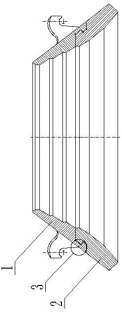
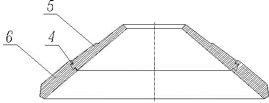

Image

  • Cone sand making machine two-component rolling sand making cavity assembly and production method thereof
  • Cone sand making machine two-component rolling sand making cavity assembly and production method thereof
  • Cone sand making machine two-component rolling sand making cavity assembly and production method thereof

Examples


Embodiment 1

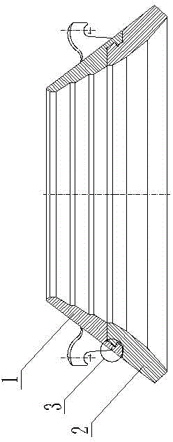
[0014] Embodiment 1: with reference to attached Figure 1-3 . A two-component rolling sand chamber assembly for a conical sand making machine, the upper part 1 of the rolling mortar wall is made of Mn13, the lower part 2 of the rolling mortar wall is made of high-carbon chromium steel, and there is an annular groove on the outer or inner wall of the lower part of the rolling mortar wall and is connected with the The annular groove on the inner or outer wall of the upper part of the rolling mortar wall forms a concave-convex casting fit 3; the upper part 5 of the crushing wall is Mn13, the lower part 6 of the crushing wall is high-carbon chromium steel, and there is an annular groove on the outer or inner wall of the lower part of the crushing wall and is connected with the upper part of the crushing wall The annular groove on the inner wall or the outer wall forms a concavo-convex casting fit 4 . A trumpet-shaped casting runner is arranged along the upper groove of the annula...

Embodiment 2

[0015] Example 2: On the basis of Example 1, a method for manufacturing a two-component rolling sand chamber assembly of a conical sand making machine, making the wall of the rolling mortar: (1) Making the casting mold for the lower part of the wall of the rolling mortar according to conventional techniques And there are grooves on the outer wall or inner wall of the lower mold of the rolling mortar wall casting mold to form a clamping mold. The lower mold of the lower casting mold of the rolling mortar wall is placed on a high-frequency vibration platform, and the molten material is melted under the vibration of the high-frequency vibration platform. The high carbon chromium steel is cast into the casting mold of the lower part of the rolling mortar wall, and the lower part of the rolling mortar wall is obtained after cooling and forming, and then the lower part of the rolling mortar wall is heat treated; (2) The groove clamping part of the lower part of the rolling mortar wall...


PUM

PropertyMeasurementUnit
hardnessaaaaaaaaaa

Abstract

The invention relates to a cone sand making machine two-component rolling sand making cavity assembly and a production method thereof. According to the invention, the upper part of a rolling mortar wall is made of Mn13, a lower part of the rolling mortar wall is high-carbon chromium steel, an ringed groove is arranged at outer wall or inner wall of the lower part of the rolling mortar wall, and the ringed groove can form concave-convex fusion casting cooperation with a ringed groove on the inner wall or outer wall at upper part of the rolling mortar wall, the upper part of a crushing wall is made of Mn13, a lower part of the crushing wall is made of high-carbon chromium steel, a ringed groove is arranged at outer wall or inner wall of the lower part of the crushing wall, and the ringed groove can form concave-convex fusion cooperation with a ringed groove on the inner wall or outer wall at upper part of the crushing wall. The method has the following advantages that 1)during a sand making process, wear extent of the rolling mortar wall and the crushing wall is different by stone with different specification, defect that a groove is formed on the rolling sand making cavity so that sands can not be produced due to little wearing at upper part of the rolling mortar wall and the crushing wall as well as large wearing at lower part of the rolling mortar wall and the crushing wall can be solved; and 2)wear extent of Mn13 at upper part of the rolling mortar wall and the crushing wall generated during stone crushing is relatively consistent with the wear extent of the rolling sand making cavity at lower part of the high-carbon chromium steel rolling mortar wall.

Description

technical field [0001] The invention relates to a cone sand making machine, which can not only meet the wear-resisting requirements of gravel crushing but also meet the wear-resistant requirements of rolling and compacting sand during the sand making process. The assembly and the manufacturing method belong to the field of assembly manufacturing of cone sand making machine components. Background technique [0002] CN102350388A, the name "high chromium rolling mortar wall assembly for conical sand making machine", it includes the rolling mortar wall assembly, and it is characterized in that: the material of the rolling mortar wall is high chromium white wear-resistant cast iron, and its chromium content is greater than or equal to 9%, equal to or less than 32%. Advantages: First, the wear resistance of the rolling mortar wall is greatly improved, and its wear resistance is about 5 times that of the current Mn13 rolling mortar wall. Not only the service life is greatly extend...

Claims


Application Information

Patent Timeline
Patent Type & Authority Applications(China)
IPC IPC(8): B02C2/00B23P15/00
Inventor 胡祖尧胡建明王永清
Owner ZHEJIANG SHUANGJIN MACHINERY HLDG
Learn More