High speed spindle box structure

A high-speed spindle and spindle technology, which is applied in the direction of large fixed members, metal processing machinery parts, maintenance and safety accessories, etc., can solve the problems that the bearing affects the speed and processing accuracy, and the cooling effect is not good, so as to ensure the processing accuracy and increase the speed , Guarantee the effect of rotation accuracy

Active Publication Date: 2015-09-09
浙江日发精密机床有限公司
View PDF5 Cites 25 Cited by
  • Summary
  • Abstract
  • Description
  • Claims
  • Application Information

AI Technical Summary

Problems solved by technology

[0003] The purpose of the present invention is to overcome the defects of poor cooling effect and easy temperature rise of the bearings in the existing headstock mechanism, which affects the speed and machining accuracy, and provide a high-speed motor with good cooling and lubrication effects, high machining accuracy and long service life of the bearings. Headstock structure

Method used


Image

  • High speed spindle box structure
  • High speed spindle box structure
  • High speed spindle box structure

Examples


Embodiment Construction

[0016] Specific embodiments of the present invention will be described in detail below in conjunction with the accompanying drawings.

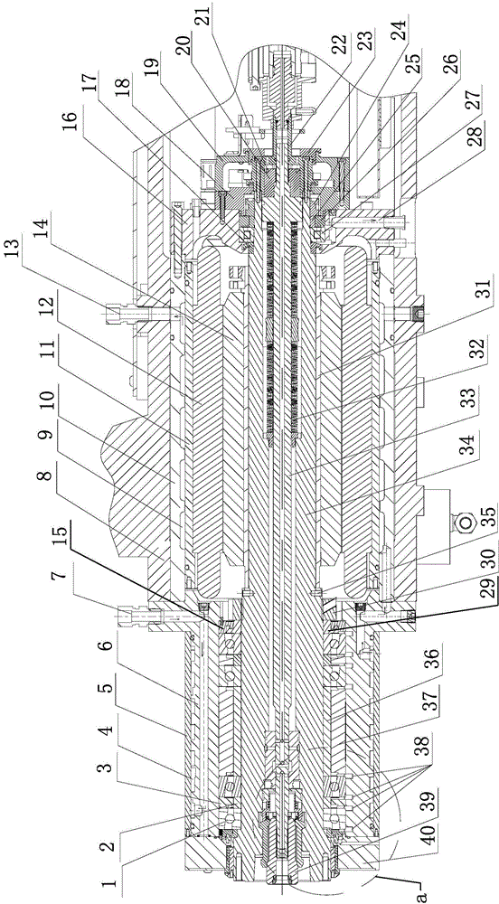
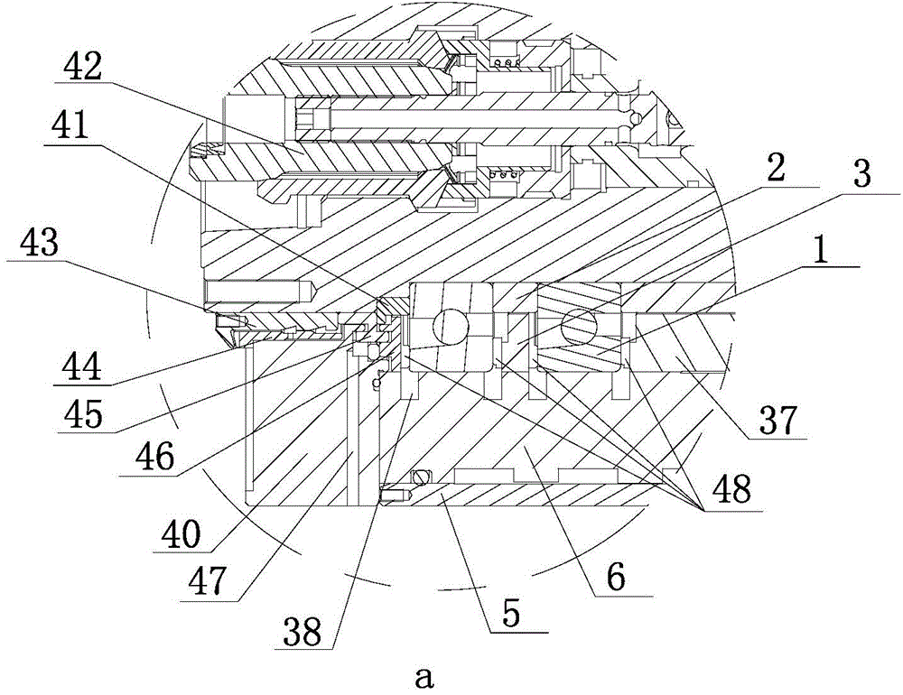
[0017] Such as Figure 1~Figure 6 As shown, the present invention includes a main shaft housing 8, a main shaft device, a front bearing seat 6, a rear bearing housing 16, a main shaft drive mechanism and a dynamic balance adjustment mechanism, the main shaft housing 8 is provided with a main shaft hole, and the main shaft The device comprises a hollow main shaft 34, a broach bar 33, a broach claw and a disc spring group 32, the main shaft 34 is worn in the main shaft hole, and the disc spring group 32, the broach claw 39 and the broach bar 33 are accommodated. Placed in the hollow inner cavity of the main shaft 34, the broach claw cover 42 is mounted on the front end of the broach rod 33, and the broach claw cover 42 is fixed between the broach claw 39 and the inner cavity wall at the front end of the main shaft 34. The butterfly spring group...


PUM


Abstract

The invention discloses a high speed spindle box structure, and belongs to the machine tool part device field. The high speed spindle box structure comprises a spindle box, a spindle device, a front bearing seat, a rear bearing seat, a spindle drive mechanism, a cooling system, a lubrication system and a dynamic balance regulating mechanism, wherein a spindle of the spindle device is supported by a front bearing component and a rear bearing component, and installed in a spindle hole in the spindle box, bearings of the front bearing component are two pairs of front ball bearings and rear ball bearings, which are arranged at a certain interval, bearings of the rear bearing component are roller bearings, the cooling system comprises a spindle cooling mechanism and a bearing cooling mechanism which respectively have functions of cooling the spindle and cooling the interiors of the bearings, and the lubrication system comprises a front bearing lubrication mechanism and a rear bearing lubrication mechanism, and respectively have functions of lubricating the front bearing component and lubricating the rear bearing component. The high speed spindle box structure solves the problems that an existing spindle box mechanism is poor in cooling effect, temperature of bearings of the existing spindle box mechanism easily rise, and then rotation speed and processing accuracy of the existing spindle box mechanism are influenced.

Description

technical field [0001] The invention belongs to the field of machine tool parts and devices, and in particular relates to a high-speed spindle box structure. Background technique [0002] The existing spindle box structure generally includes a spindle box, a spindle device, a front bearing seat, a rear bearing seat and a spindle drive mechanism, the spindle box is provided with a spindle hole, and the spindle device includes a hollow spindle, a pull Knife rod, broaching claw and disc spring group, the main shaft is installed in the main shaft hole, the front bearing seat and the rear bearing seat are respectively installed at the front and rear ends of the main shaft hole, and the front and rear bearing seats are provided with the main shaft. Concentric axial through hole, the front end of the main shaft is supported on the axial through hole of the front bearing seat through the front bearing, and the rear end of the main shaft is installed on the axial through hole of th...

Claims


Application Information

Patent Timeline
Patent Type & Authority Applications(China)
IPC IPC(8): B23B19/02B23Q11/12
CPCB23Q1/70B23Q11/123B23Q11/126B23Q11/127
Inventor 石鑫江周德润汤海锋
Owner 浙江日发精密机床有限公司
Why Eureka
Try Eureka