Injection mold and molding method

A technology of injection mold and molding cavity, which is applied in the direction of coating, etc., can solve the problems of difficult injection molding of carbon fiber composite materials, and achieve the effect of simple and practical molding method, high carbon fiber content and high strength

Inactive Publication Date: 2015-09-09
QUNDA PLASTIC ELECTRONICS SHENZHEN
View PDF6 Cites 1 Cited by
  • Summary
  • Abstract
  • Description
  • Claims
  • Application Information

AI Technical Summary

Problems solved by technology

[0005] The technical problem to be solved by the present invention is to provide a simple and practical injection mold for carbon fiber composite materials and its molding method for the problem that it is difficult to use carbon fiber composite materials for injection molding in products in the prior art

Method used


Image

  • Injection mold and molding method
  • Injection mold and molding method

Examples


Embodiment Construction

[0019] In order to make the object, technical solution and advantages of the present invention clearer, the present invention will be further described in detail below in conjunction with the accompanying drawings and embodiments. It should be understood that the specific embodiments described here are only used to explain the present invention, not to limit the present invention.

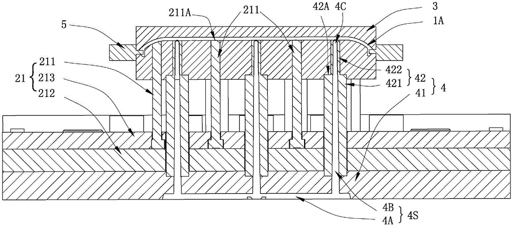
[0020] For the convenience of description, when "up", "down", "left", "right" and so on referred to in the following indicate directions ("the ejection bottom plate 212 is fixedly connected to the flow channel plate 41", etc. do not mean Orientation is not included) is consistent with the up, down, left, and right directions of the attached drawing itself, and only represents relative positional features.

[0021] see figure 1 , figure 1 It is a structural schematic diagram of an injection mold of a preferred embodiment of the present invention. In this embodiment, the injection mold includes a ...


PUM

PropertyMeasurementUnit
diameteraaaaaaaaaa

Abstract

The invention provides an injection mold for molding of a carbon fiber composite material outer shell; the injection mold comprises a fixed mold, a movable mold and a runner system; the runner system forms runners having a plurality of pouring gates communicated with a molding cavity of the injection mold. The invention also provides a molding method using the injection mold, wherein the molding method comprises the steps: the fixed mold and the movable mold are assembled, so that the pouring gates are communicated with the molding cavity; a carbon fiber composite material successively passes through a main runner and sub-runners and then is injected into the molding cavity by the plurality of pouring gates, and thus the outer shell is obtained; and the fixed mold and the movable mold are opened, the outer shell is pushed out from one side of the fixed mold through a thimble and is separated from the injection mold. The injection mold and the molding method are simple and practical, are suitable for injection molding of the carbon fiber composite material, and have low requirement on liquidity of the carbon fiber composite material which can be molded; and the carbon fiber content of the carbon fiber composite material which can be subjected to injection molding is higher, and the molded carbon fiber composite material outer shell has higher strength.

Description

technical field [0001] The invention relates to the field of molds, in particular to an injection mold used for forming a carbon fiber composite shell and a forming method thereof. Background technique [0002] Carbon fiber is a fibrous carbon material. Each carbon fiber is composed of thousands of smaller carbon fibers, with a diameter of about 5 μm to 8 μm. It is a new type of material with higher strength than steel, lower density than aluminum, stronger corrosion resistance than stainless steel, higher temperature resistance than heat-resistant steel, and electrical conductivity like copper. It has many valuable electrical, thermal and mechanical properties. Carbon fiber not only has the inherent intrinsic characteristics of carbon materials, but also has the softness and processability of textile fibers. It is a new generation of reinforcing fibers. Carbon fiber is generally not used alone, but is mostly added to resin, metal, ceramics, concrete and other materials as...

Claims


Application Information

Patent Timeline
Patent Type & Authority Applications(China)
IPC IPC(8): B29C45/26B29C45/27B29C45/40B29C45/00
CPCB29C45/26B29C45/0005B29C45/27B29C45/4005
Inventor 汪智勇周华民尹高喜唐均华
Owner QUNDA PLASTIC ELECTRONICS SHENZHEN
Why Eureka
Try Eureka