Layered flood-discharging and sediment-flushing device for reservoir

A flood discharge and reservoir technology, applied in water conservancy projects, sea area engineering, coastline protection, etc., can solve problems such as reservoir capacity loss, turbidity, reservoir function and safety impact, and achieve the effect of opening and closing gates conveniently and avoiding huge impacts

Active Publication Date: 2015-09-09
XI'AN UNIVERSITY OF ARCHITECTURE AND TECHNOLOGY
View PDF9 Cites 6 Cited by
  • Summary
  • Abstract
  • Description
  • Claims
  • Application Information

AI Technical Summary

Problems solved by technology

If the inflow of water with high sediment content in the flood season is not eliminated in time, part of the muddy water will flow back into the reservoir at the dam, gradually causing muddy water to flow in the entire reservoir, and the reservoir water will become turbid and the water quality will deteriorate , which increases the difficulty and cost of water treatment in the waterworks and affects the safety of drinking water; at the same time, the sediment in the inflow of water will also deposit in the reservoir, causing a large loss of reservoir capacity and seriously affecting the function and safety of the reservoir
[0004] Sediment discharge during the flood season is the main technical method to solve the sedimentation of the reservoir. At present, the flood discharge and sediment discharge devices of the reservoir only have a flood discharge outlet at the bottom next to the dam. It flows in layers, and the specific flow position is related to the inflow flow of the reservoir and the content of sediment

Method used


Image

  • Layered flood-discharging and sediment-flushing device for reservoir
  • Layered flood-discharging and sediment-flushing device for reservoir
  • Layered flood-discharging and sediment-flushing device for reservoir

Examples


Embodiment Construction

[0024] The present invention will be described in further detail below in conjunction with the accompanying drawings.

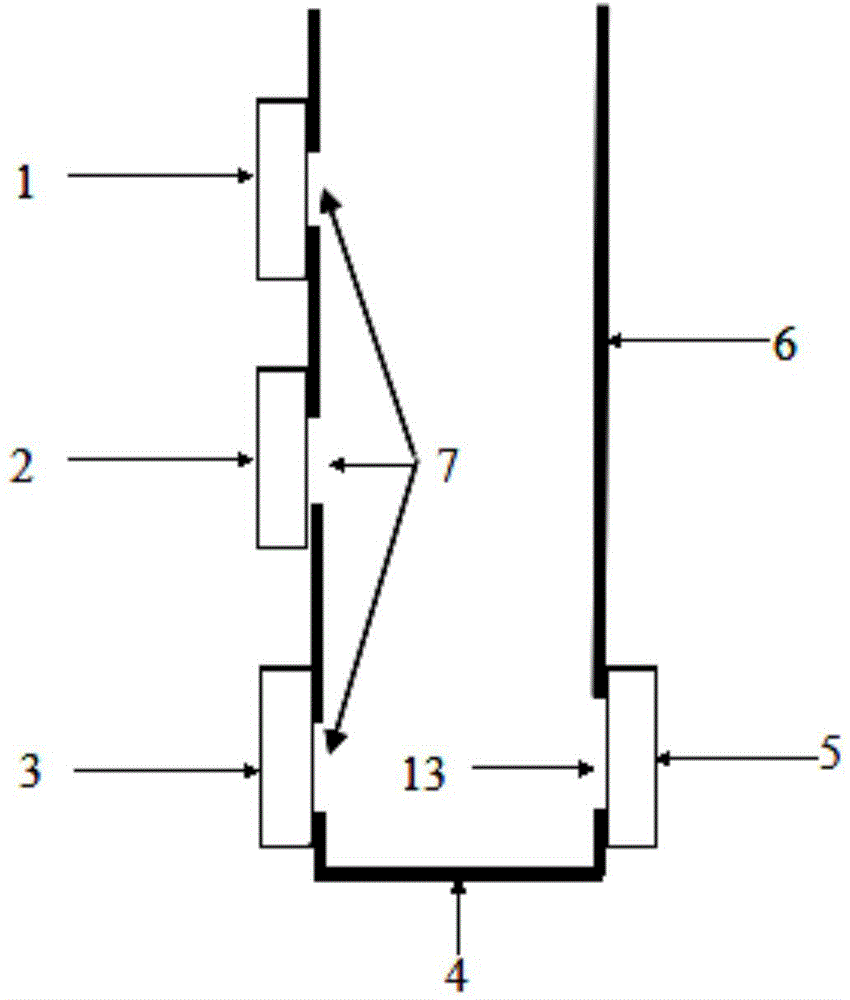
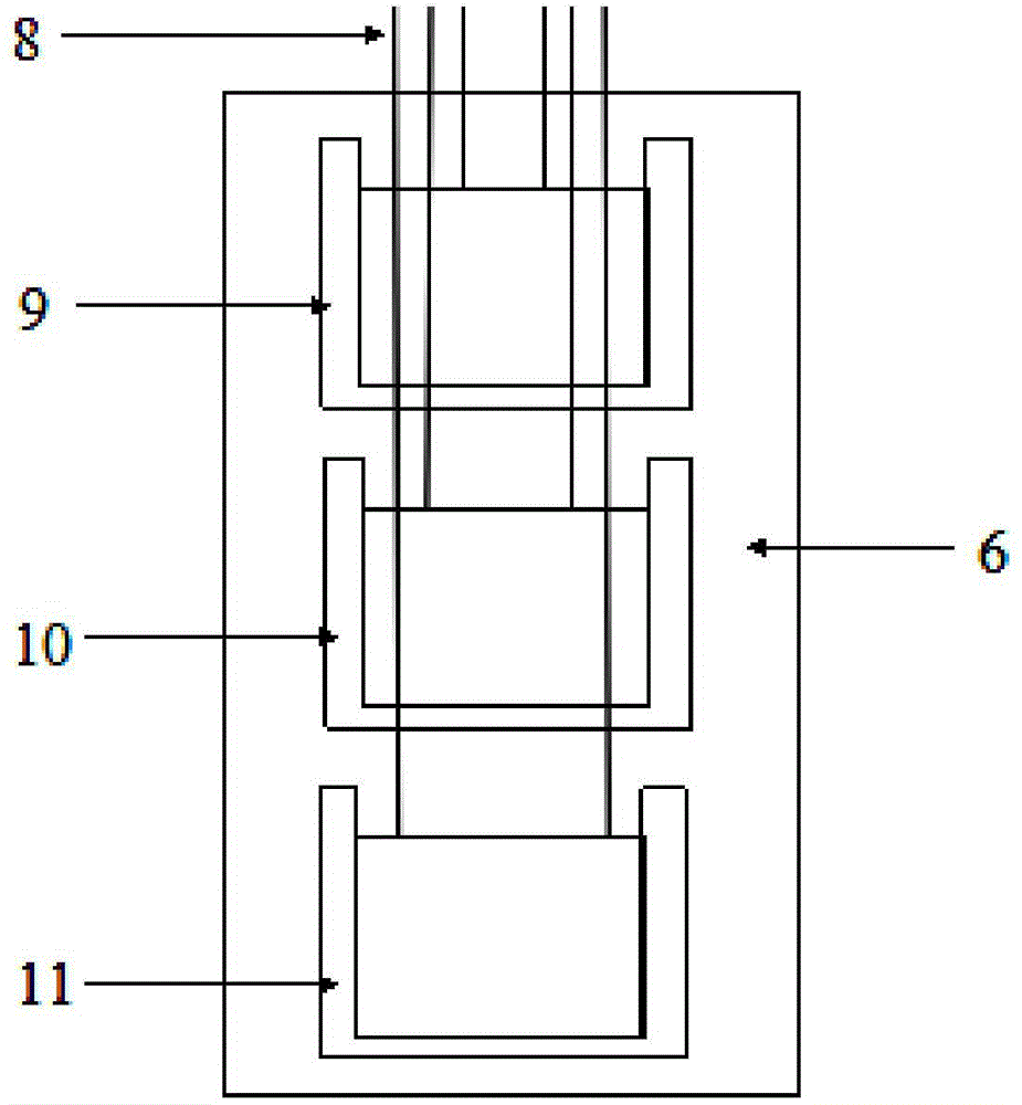
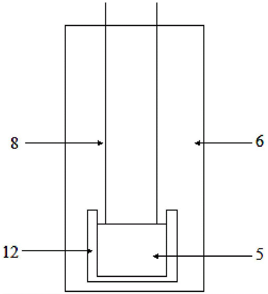
[0025] see figure 1 , a layered flood discharge and sand discharge device for reservoirs according to the present invention, its core idea is to set three flood discharge gates at three typical water depths where muddy water may exist in the surface layer, middle layer, and bottom layer according to the typical water level of the reservoir in the flood season. The layered flood discharge gates are reasonably assembled in a set of devices. According to the measured muddy water area, the layered flood discharge gates that need to be opened under different rainstorm conditions are determined to remove the muddy water in time. At the same time, in order to reduce the flow of water during flood discharge The impact force on the side wall and bottom of the device is determined to adopt the working method of maintaining the connection between the layered flood disch...


PUM


Abstract

The invention discloses a layered flood-discharging and sediment-flushing device for a reservoir. The layered flood-discharging and sediment-flushing device comprises a dam body with a U-shaped longitudinal cross section, wherein the dam body comprises two oppositely arranged side walls (6) and a connecting section (4) for connecting the bottoms of the two side walls (6); three flood discharging openings (7) are formed in the side wall (6) of one side close to the reservoir from top to bottom in sequence; a surface layer flood discharging gate (1), a middle layer flood discharging gate (2) and a bottom flood discharging gate (3) are arranged on the three flood discharging openings (7); a bottom water outlet (13) is formed in the bottom of the side wall (6) of one side away from the reservoir; a water outlet gate (5) is arranged on the bottom water outlet (13); the layered flood-discharging and sediment-flushing device is communicated with a reservoir water body through the flood discharging openings (7). According to the invention, the layered flood-discharging and sediment-flushing device is simple in structure, can discharge muddy water timely, is firm and durable, and can operate stably for long term.

Description

Technical field: [0001] The invention belongs to the field of reservoir silt control, and relates to a reservoir silt discharge device, in particular to a reservoir layered flood discharge and sand discharge device based on the law of vertical layered flow of muddy water in the reservoir. Background technique: [0002] Water is becoming more and more scarce in the world, and reservoirs are gradually becoming the main water supply source for most cities, but sedimentation is a thorny problem faced by almost every reservoir. On the one hand, sediment deposition will reduce the effective storage capacity of the reservoir, and the world’s reservoir storage capacity loses an average of 4.5 billion cubic meters per year, which is about 0.64% of the total storage capacity; while the annual siltation loss rate of my country’s reservoirs is the highest in the world, higher than the world average 2 to 3 times. For example, since the Three Gorges Reservoir of the Yangtze River was impou...

Claims


Application Information

Patent Timeline
Patent Type & Authority Applications(China)
IPC IPC(8): E02B8/04E02B8/02
Inventor 孙昕吴铮张海涵
Owner XI'AN UNIVERSITY OF ARCHITECTURE AND TECHNOLOGY
Why Eureka
Try Eureka