Hydraulic oil tank for road roller

A technology of hydraulic oil tank and road roller, which is applied in the direction of oil supply tank device, mechanical equipment, fluid pressure actuating device, etc., can solve the problems of waste of raw materials, environmental pollution, inconvenient replacement of oil suction filter elements, etc.

Inactive Publication Date: 2015-09-09
JIANGSU KUI ZE MACHINERY IND CO LTD
View PDF6 Cites 5 Cited by
  • Summary
  • Abstract
  • Description
  • Claims
  • Application Information

AI Technical Summary

Problems solved by technology

[0003] One is that it is inconvenient to replace the oil-absorbing filter element. The oil-absorbing filter element is installed at the bottom of the oil tank through the filter element mounting seat, so before replacing the oil-absorbing filter element, all the hydraulic oil in the hydraulic oil tank must be drained; The installation position is lower than the minimum liquid level of the hydraulic oil tank, and the oil suction pipe is installed at the bottom of the hydraulic oil ta

Method used


Image

  • Hydraulic oil tank for road roller

Examples


Embodiment

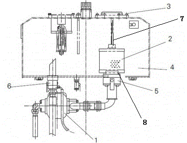
[0027] Such as figure 1 As shown, a hydraulic oil tank of a road roller in this embodiment includes: a hydraulic pump 1, an oil suction filter element 2, a top cover 3, a hydraulic oil tank 4, an oil suction stop valve 5, and an oil return stop valve 6; one end of the hydraulic pump 1 passes through the oil suction pipe and The hydraulic oil tank 4 is connected; the other end of the hydraulic pump 1 is connected to the hydraulic oil tank 4 through the oil return pipe; the oil suction filter element 2 is set at the oil inlet pipe at the bottom of the hydraulic oil tank 4; the top cover 3 is set at the top of the hydraulic oil tank 4; the oil suction stop valve 5 is set at On the oil suction pipe; the oil return cut-off valve 6 is set on the oil return pipe. The hydraulic oil tank 4 also includes a pressure rod 7 which is arranged under the top cover 3 . The oil suction filter element 2 is fixed on the oil inlet pipe at the bottom of the hydraulic oil tank 4 through a pressur...


PUM


Abstract

The invention discloses a hydraulic oil tank for a road roller. The hydraulic oil tank comprises a hydraulic pump, an oil absorbing filter element, a top cover, a hydraulic oil tank, an oil absorbing stop valve and an oil returning stop valve; one end of the hydraulic pump is connected with the hydraulic oil tank through an oil absorbing pipe, and while the other end of the hydraulic pump is connected with the hydraulic oil tank through an oil returning pipe; the oil absorbing filter element is arranged at an oil feeding pipe at the bottom part of the hydraulic oil tank; the top cover is arranged on the top part of the hydraulic oil tank; the oil absorbing stop valve is arranged on the oil absorbing pipe; the oil returning stop valve is arranged on the oil returning pipe. According to the hydraulic oil tank for the road roller, the structure of the traditional oil tank is improved, namely, the mounting mode of the oil absorbing filter element is mainly improved; the stop valves are mounted at the oil absorbing pipe and the oil returning pipe of the hydraulic oil tank; the improved hydraulic oil tanks are avoided discharging of all hydraulic oil, so that the labor intensity of repair workers can be greatly reduced; in addition, secondary pollution of the hydraulic oil due to oil discharging can be avoided.

Description

technical field [0001] The invention relates to the field of road machinery, in particular to a road roller hydraulic oil tank. Background technique [0002] At present, the hydraulic oil tank of the traditional road roller in the prior art includes oil suction filter element, filter element mounting seat, hydraulic oil tank, hydraulic pump, oil suction pipe and other components, but this type of hydraulic oil tank has the following two defects: [0003] One is that it is inconvenient to replace the oil-absorbing filter element. The oil-absorbing filter element is installed at the bottom of the oil tank through the filter element mounting seat, so before replacing the oil-absorbing filter element, all the hydraulic oil in the hydraulic oil tank must be drained; The installation position is lower than the minimum liquid level of the hydraulic oil tank, and the oil suction pipe is installed at the bottom of the hydraulic oil tank. When the hydraulic pump needs to be replaced a...

Claims


Application Information

Patent Timeline
IPC IPC(8): F15B21/04F15B1/26
CPCF15B21/041F15B1/26
Inventor 陈奎
Owner JIANGSU KUI ZE MACHINERY IND CO LTD
Why Eureka
Try Eureka