Liquid magnetic levitation axial-flow type heart auxiliary blood pump

A magnetic levitation shaft and heart assisting technology, applied in blood pumps, hypodermic injection devices, suction devices, etc., can solve the problems of many dead angles of blood flow, large volume of blood-passing parts, mechanical hemolysis and thrombus, etc. The effect of less dead space, increasing the area of ​​the inlet channel, and reducing the chance of thrombus

Active Publication Date: 2014-11-26
CHANGZHI JIUAN ARTIFICIAL HEART TECH DEV
View PDF8 Cites 6 Cited by
  • Summary
  • Abstract
  • Description
  • Claims
  • Application Information

AI Technical Summary

Problems solved by technology

When the impeller rotates at high speed, the "shaft-bearing" is easy to wear. First, there is vibration, and as the amount of wear gradually increases, the vibration intensifies, and then there are problems such as blade bumping, mechanical failure, and pump stop, and collision and friction heat will also occur. Cause severe complications such as mechanical hemolysis and thrombosis, which can lead to death of the patient
[0003] The known axial-flow blood pump also adopts a suspension bearing system, which has become a popular trend. At present, this suspension bearing system basically adopts an active magnetic suspension structure. Although the problems of wear, vibration and heat generation are solved, the life of the pump is long and the mechanical Sexual hemolysis is relatively light, but the active magnetic levitation structure is a closed-loop control system composed of position sensors, rate amplifiers, controllers, etc., with complex structure, large volume of blood-passing parts, many dead angles and large areas of blood flow, and the problem of thrombus is more prominent , which also seriously affects the use of the pump

Method used


Image

  • Liquid magnetic levitation axial-flow type heart auxiliary blood pump
  • Liquid magnetic levitation axial-flow type heart auxiliary blood pump
  • Liquid magnetic levitation axial-flow type heart auxiliary blood pump

Examples


Embodiment Construction

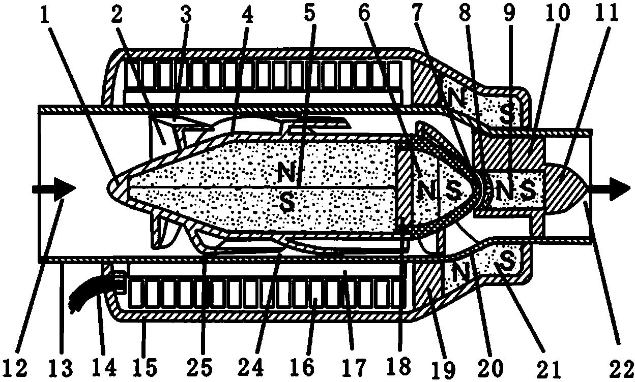
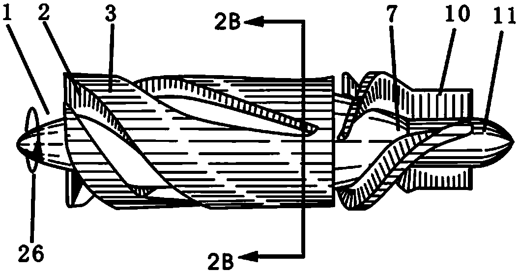
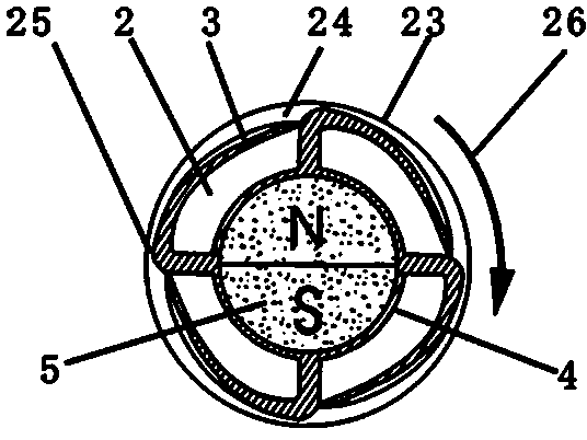
[0021] The present invention is a "pump-machine assembly" composed of a pump system and a driving motor system. The pump system is composed of a pump pipe 13, an impeller 1, an impeller hub 4, a rear guide vane 10, and a rear guide vane hub 11. The front end of the impeller The leading vane is removed; the drive motor system is composed of the inner permanent magnet rotor 5, the stator core 16, the stator coil winding 17, the motor casing 15, and the energy supply wire 14; the inner permanent magnet rotor 5 of the drive motor system is embedded in the impeller of the pump system In the hub 4, the outer edge of each blade 2 of the impeller 1 has an inclined roof eaves 3, and the roof eaves 3 and the inner wall 23 of the pump tube form an inlet 24 and an outlet 25, and make the inlet 24 large, The outlet 25 is small. When the impeller 1 rotates in the direction of rotation 26, most of the blood flows through the main channel between the blades, and a small part of the blood flows...


PUM


Abstract

The invention relates to a special blood pump, in particular to a liquid magnetic levitation axial-flow type heart auxiliary blood pump which is implanted into a human body. The liquid magnetic levitation axial-flow type heart auxiliary blood pump is composed of a pump system and a motor system. The liquid magnetic levitation axial-flow type heart auxiliary blood pump is characterized in that the top of a spiral blade of an impeller is provided with an inclined top brim so that a flow feeding opening can be large and a flow discharging opening can be small; an axial magnetic cone is arranged on the rear segment in a hub of the impeller, an axial magnetic pillar is arranged in a hub of a rear guide blade, and the opposite magnetic poles of the two magnets are opposite; an axial magnetic ring is arranged in a motor shell and outside the rear segment of a pump pipe, and the opposite magnetic poles of the axial magnetic ring and the axial magnetic cone in the hub of the impeller are also opposite; a pair of protruding cover-pit sliding bearings at the rear end of the impeller have the radial and axial positioning function on the impeller when the impeller is started, the radial center positioning function generated by mutual attraction of the magnetic cone and the magnetic pillar is also achieved, and therefore the impeller can stably enter a levitation state; the rear segment of the pump pipe conducts reducing to achieve the functions of increasing pressure and improving the efficiency of the blood pump; front guide blade is removed from the front end of the impeller, the inlet flow area can be increased, and the function of improving the efficiency of the blood pump is achieved.

Description

technical field [0001] The invention relates to a special blood pump, in particular to a liquid magnetic levitation axial-flow heart-assisted blood pump implanted in the human body in the field of biomedical engineering. Background technique [0002] The "heart assist blood pump" that is widely used clinically is mainly the "axial flow blood pump". Most of the known axial-flow blood pumps use a "shaft-bearing" impeller support system, and the pump tube of the pump body is sequentially arranged with a leading vane, an impeller, and a rear guiding vane. There is a shaft in the center of the impeller, and two sliding bearings are respectively inlaid in the center of the front and rear guide vanes to support the rotation of the shaft and the impeller. When the impeller rotates at high speed, the "shaft-bearing" is easy to wear. First, there is vibration, and as the amount of wear gradually increases, the vibration intensifies, and then there are problems such as blade bumping, ...

Claims


Application Information

Patent Timeline
Patent Type & Authority Applications(China)
IPC IPC(8): A61M1/12
CPCA61M60/148A61M60/205A61M60/871
Inventor 彭远仪万峰李国荣陈海丰田步升郝宗超祝会占
Owner CHANGZHI JIUAN ARTIFICIAL HEART TECH DEV
Why Eureka
Try Eureka