

Solenoid valve with valve core structure
A solenoid valve and spool technology, applied in sliding valves, valve devices, engine components, etc., can solve problems such as low precision, large hydraulic shock, slow response of engineering equipment, etc., to achieve reduced variation, response speed and control accuracy Improved effect
- Summary
- Abstract
- Description
- Claims
- Application Information
AI Technical Summary
Problems solved by technology
Method used
Image

Examples
Embodiment
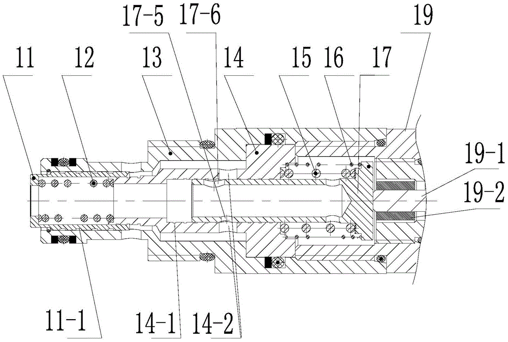
[0029] Such as Figures 1 to 4 shown. A solenoid valve with a spool structure of the present invention comprises a valve sleeve 13, a connector 19 of the valve sleeve 13, a valve core 17, a pressure reducing valve core 11 and a throttle valve sleeve 14 arranged in the valve sleeve 13; The valve core 11 is arranged at one end of the valve sleeve 13, and the throttle valve sleeve 14 is arranged at the other end of the valve sleeve 13; the valve core 17 is arranged in the throttle valve sleeve 14;
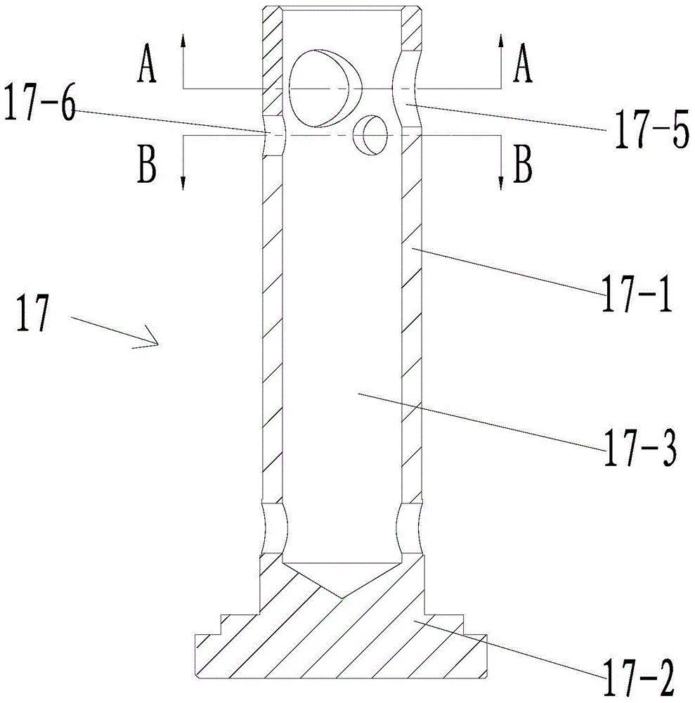
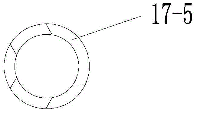
[0030] The valve core 17 includes a valve stem body 17-1 and a valve seat 17-2, and the shaft center of the valve stem body 17-1 is provided with an oil guide blind hole 17-3; the valve stem body 17-1 guides oil The end of the inlet of the blind hole 17-3 is provided with an oil guide hole connected to the oil guide blind hole 17-3 along the circumference;
[0031] The other end circumference of the valve stem body 17-1, that is, the bottom circumference of the oil guide blind hole ...
PUM
 Abstract
Description
Claims
Application Information