
Relay closing moment detecting method

A detection method and a technology of closing time, which are applied in the direction of electrical unknown time interval measurement, instruments, and devices for measuring time intervals, etc., can solve problems affecting normal use, inrush current, and tripping of AC power circuit breakers, etc., to achieve extended use Effect of small life and inrush current

Active Publication Date: 2015-09-09
JIANGSU GOODWE POWER SUPPLY TECHNOLOGY CO LTD
View PDF7 Cites 7 Cited by
  • Summary
  • Abstract
  • Description
  • Claims
  • Application Information

AI Technical Summary

Problems solved by technology

But in fact: (1) The relay is a mechanical switch, and the delay time difference of different individuals is different; (2) affected by the PCB wiring, the delay time difference of the same relay on different PCBs is different; (3) After using the same relay for a period of time, the delay time difference will also change; when the delay time difference of the relay changes due to the above reasons, and it is not closed at the zero crossing point of the AC power supply, it will cause an inrush current and affect the use of the relay and the machine life
When the impact current reaches a certain threshold, it will cause the circuit breaker on the AC power supply side to trip, affecting normal use

Method used


Image

  • Relay closing moment detecting method
  • Relay closing moment detecting method
  • Relay closing moment detecting method

Examples


Embodiment Construction

[0012] Below in conjunction with the embodiment shown in the accompanying drawings, the present invention is described in detail as follows:

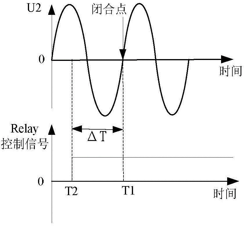
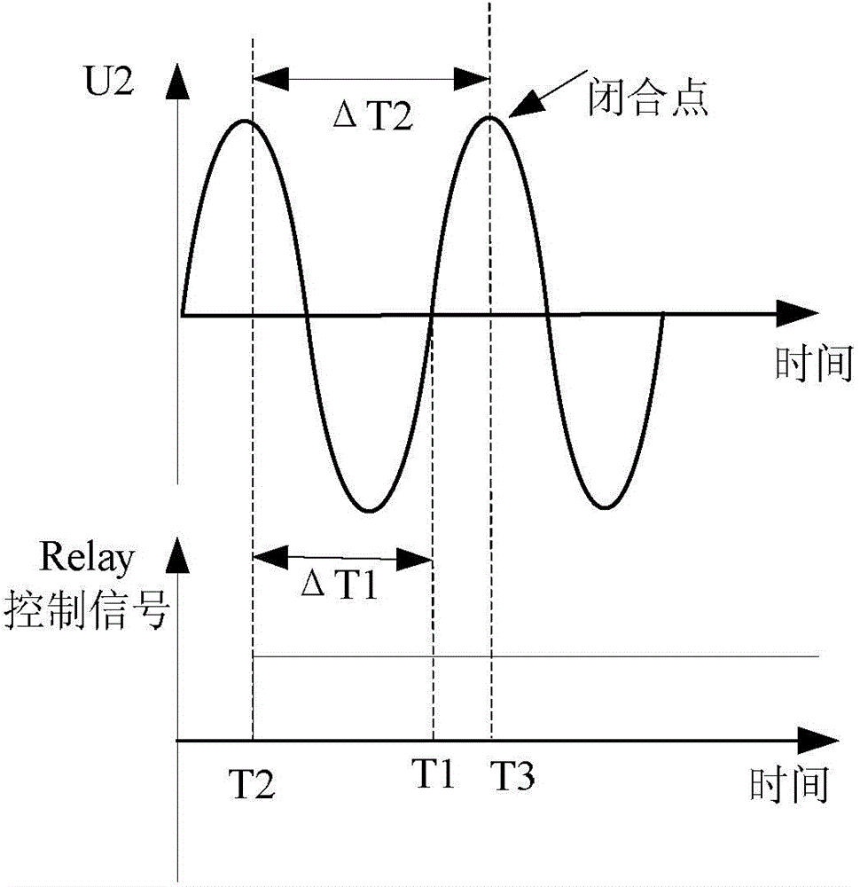
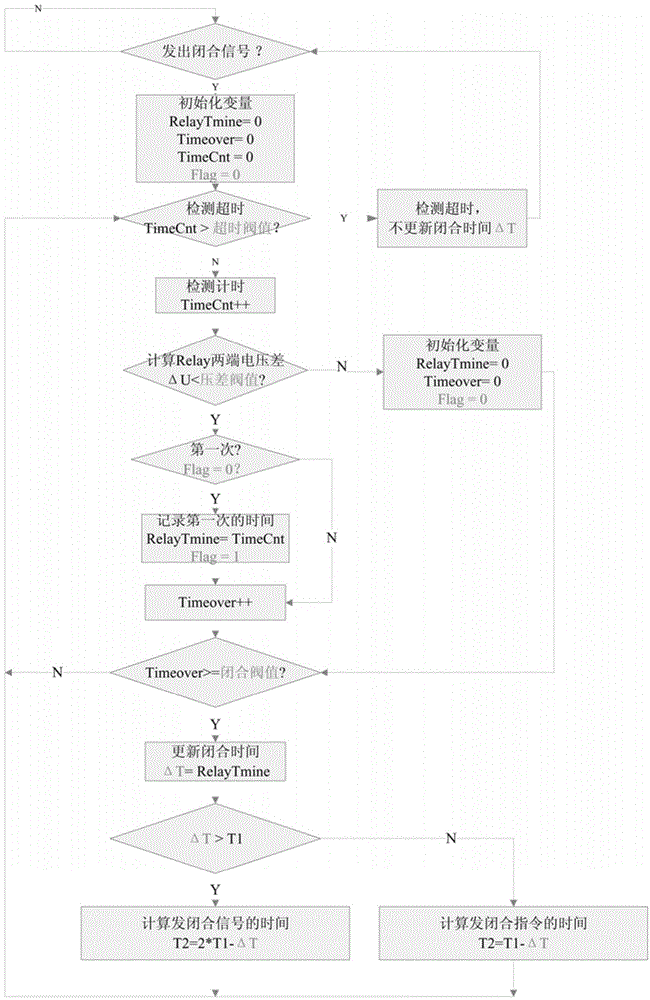
[0013] Such as image 3 As shown, the definition: the AC power cycle is T1, and each cycle of the AC power is timed by a timer. This timing variable changes periodically, and the timing variable cycle is equal to the AC power cycle. The time when the relay control chip needs to issue a closing command is T2 , T2T1, the time T2 when the relay control chip sends the closing signal next time is 2*T1 -ΔT, when ΔT≤T1, the moment T2 when the relay control chip sends a closing signal next time is T1-ΔT. The delay time difference ΔT for the first closing of the relay is the default value provided by the manufacturer. After the relay control chip sends a closing command to start timing, the time variable TimeCnt needs to be compared with the timeout threshold. If TimeCnt is greater than the timeout threshold, timeout is detected and the delay ...


PUM


Abstract

The invention relates to a relay closing moment detecting method. Timing is started from the moment that a relay control chip gives out a closing instruction, the difference value delta U on the two sides of a relay is detected in real time, if delta U is smaller than a threshold value for a certain continuous time, it is regarded that the relay is closed, the time value corresponding to the moments with delta U smaller than the threshold value serves as the time delay difference of the relay for the control chip to calculate the moment for sending a closing instruction when the relay is closed next time, it is guaranteed that the relay is closed at the zero crossing point of an alternating current source and the surge current is minimum, and therefore the service life of a machine is prolonged.

Description

technical field [0001] The invention relates to the field of optoelectronic technology, in particular to a method for detecting the closing moment of a relay. Background technique [0002] Normally, before the relay is closed, the voltage U1 at one end is zero, and the other end is connected to an AC power supply U2 (such as the power grid). If there is a voltage difference between the two ends of the relay at the moment of closing, the AC power supply will charge components such as the capacitor on the U1 side, generating an inrush current and affecting the service life of the components. The greater the voltage difference, the greater the inrush current. Therefore, it is necessary to make the relay close at the zero-crossing point of the AC power supply, so that the voltage difference between the two ends of the relay is zero. Let the zero-crossing moment of the alternating power supply be T1. It takes a certain amount of time from the control chip to issue a closing ...

Claims


Application Information

Patent Timeline
IPC IPC(8): G04F10/00
Inventor 黄敏方刚刘松
Owner JIANGSU GOODWE POWER SUPPLY TECHNOLOGY CO LTD
Learn More