Lightning protection radome system
A radome and antenna technology, applied in the field of radomes, can solve problems such as electromagnetic pulses and radar antennas being vulnerable to lightning strikes
- Summary
- Abstract
- Description
- Claims
- Application Information
AI Technical Summary
Problems solved by technology
Method used
Image
Examples
Embodiment 1
[0061] (radome tuned to X-band)
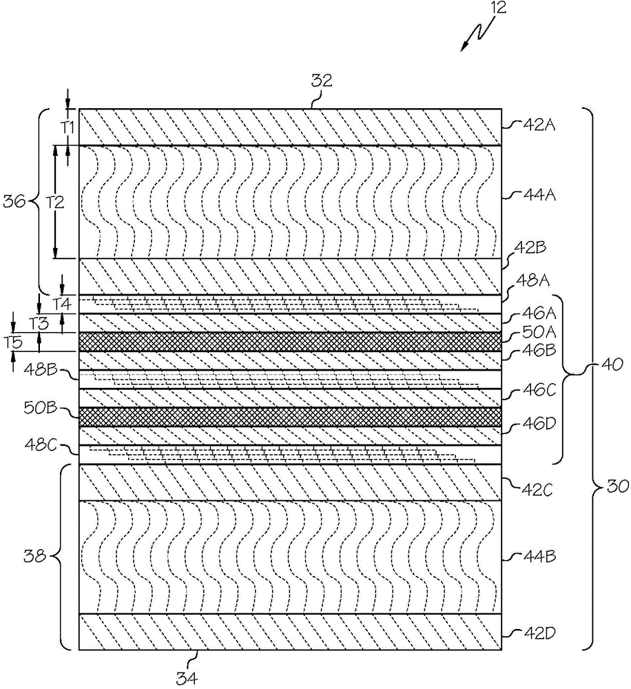
[0062] designed as figure 2 Fifteen-layer radome shown. Table 1 provides composition and thickness data.
[0063] Table 1
[0064]
[0065]
[0066] Uses a proprietary aerospace flight-tested resin-impregnated fiberglass cloth. The resin-impregnated fiberglass cloth layers (outer skin layers 42A, 42B, 42C, 42D and inner skin layers 46A, 46B, 46C, 46D) have a dielectric constant (dimensionless; measured at room temperature and 1 kHz) of approximately 3.3.
[0067] Using special aerospace flight tested syntactic foam. The syntactic foam layers (spacer layers 44A, 44B) have a dielectric constant (dimensionless; measured at room temperature and 1 kHz) of approximately 1.9.
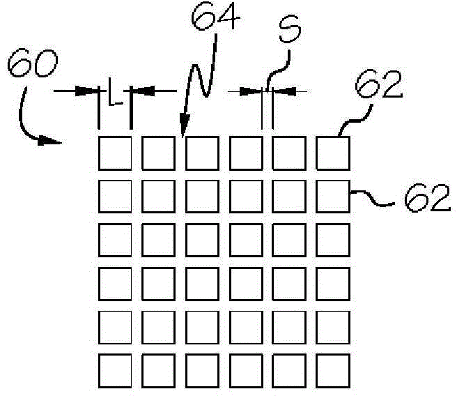
[0068] The artificial dielectric layer is configured as Figure 3A An array of metal diaphragms is shown. The size and spacing of the diaphragms in the array provides an effective capacitance of approximately 0.5 pF per artificial dielectric layer.
[0069] Th...
Embodiment 2
[0072] (radome tuned to K U frequency band)
[0073] designed as figure 2 Fifteen-layer radome shown. Table 2 provides composition and thickness data.
[0074] Table 2
[0075]
[0076]
[0077] The same dedicated aerospace flight test resin-impregnated fiberglass cloth used in Example 1 was also used in Example 2. The resin-impregnated fiberglass cloth layers (outer skin layers 42A, 42B, 42C, 42D and inner skin layers 46A, 46B, 46C, 46D) have a dielectric constant (dimensionless; measured at room temperature and 1 kHz) of approximately 3.3.
[0078] The specialized aerospace flight-tested syntactic foam used in Example 1 was also used in Example 2. The syntactic foam layers (spacer layers 44A, 44B) have a dielectric constant (dimensionless; measured at room temperature and 1 kHz) of approximately 1.9.
[0079] The artificial dielectric layer is configured as Figure 3A An array of metal diaphragms is shown. The size and spacing of the diaphragms in the array of...
Embodiment 3
[0083] (radome tuned to K A frequency band)
[0084] designed as figure 2 Fifteen-layer radome shown. Table 3 provides composition and thickness data.
[0085] table 3
[0086]
[0087]
[0088] The same dedicated aerospace flight test resin impregnated fiberglass cloth used in Examples 1 and 2 was also used in Example 3. The resin-impregnated fiberglass cloth layers (outer skin layers 42A, 42B, 42C, 42D and inner skin layers 46A, 46B, 46C, 46D) have a dielectric constant (dimensionless; measured at room temperature and 1 kHz) of approximately 3.3.
[0089] The specialized aerospace flight tested syntactic foam used in Examples 1 and 2 was also used in Example 3. The syntactic foam layers (spacer layers 44A, 44B) have a dielectric constant (dimensionless; measured at room temperature and 1 kHz) of approximately 1.9.
[0090] The artificial dielectric layer is configured as Figure 3A An array of metal diaphragms is shown. The size and spacing of the diaphragms i...
PUM
 Abstract
Description
Claims
Application Information
 - R&D Engineer
- R&D Manager
- IP Professional
- Industry Leading Data Capabilities
- Powerful AI technology
- Patent DNA Extraction
Browse by: Latest US Patents, China's latest patents, Technical Efficacy Thesaurus, Application Domain, Technology Topic, Popular Technical Reports.
© 2024 PatSnap. All rights reserved.Legal|Privacy policy|Modern Slavery Act Transparency Statement|Sitemap|About US| Contact US: help@patsnap.com


