Motor drive device, motor drive method and motor

A technology of motor drive and motor rotor, which is applied to control electromechanical transmission, control generator, motor generator control, etc., and can solve the problems of large torque ripple and uncontrollable motor current.

Active Publication Date: 2015-09-09
GUANGDONG WELLING ELECTRIC MACHINE MFG +1
View PDF5 Cites 2 Cited by
  • Summary
  • Abstract
  • Description
  • Claims
  • Application Information

AI Technical Summary

Problems solved by technology

[0008] The purpose of the present invention is to provide a motor drive device, method and motor, aiming to solve the p

Method used


Image

  • Motor drive device, motor drive method and motor
  • Motor drive device, motor drive method and motor
  • Motor drive device, motor drive method and motor

Examples


Embodiment Construction

[0062] In order to make the object, technical solution and advantages of the present invention clearer, the present invention will be further described in detail below in conjunction with the accompanying drawings and embodiments. It should be understood that the specific embodiments described here are only used to explain the present invention, not to limit the present invention.

[0063] In order to illustrate the technical solutions of the present invention, specific examples are used below to illustrate.

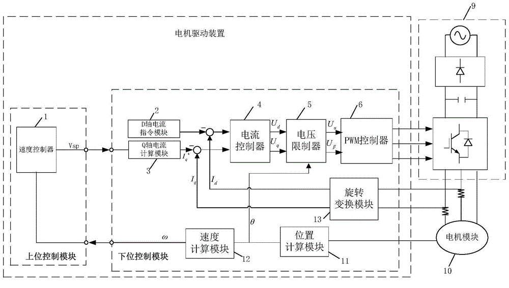
[0064] An embodiment of the present invention provides a motor drive device, such as Figure 4 Shown, a kind of motor drive device, motor drive device comprises:

[0065] The rotary converter 13 is used to output the quadrature-axis current component and the direct-axis current component after the stator current undergoes coordinate rotation transformation.

[0066] The position calculator 11 is used to detect the position of the rotor of the motor, and output a positi...


PUM


Abstract

The present invention relates to the technical field of motor control, and provides a motor drive device, a motor drive method and a motor. The motor drive device comprises a quadrature-axis voltage calculation module outputting a first quadrature-axis voltage component; a quadrature-axis current limiting module carrying out current limit to a quadrature-axis current component according to a preset quadrature-axis current so as to limit the quadrature-axis current component within a quadrature-axis current range and outputting a second quadrature-axis voltage component after calculation; an adding device obtaining the quadrature-axis voltage components; a voltage limiter performing coordinate transformation on direct-axis voltage components and the quadrature-axis voltage components according to position feedback signals and then outputting direct-axis voltage and quadrature-axis voltage; and a PWM controller converting the direct-axis voltage and quadrature-axis voltage into three-phase alternating-current voltage, realizing further control of motor current by input quadrature-axis current components and second quadrature-axis voltage component adjusted through the preset quadrature-axis current.

Description

technical field [0001] The invention relates to the technical field of motor control, in particular to a motor driving device, a method and a motor. Background technique [0002] At present, the brushless motor mainly adopts the classic vector control scheme, such as figure 1 with figure 2 As shown, the motor drive device includes an upper computer control module and a lower computer control module, wherein the upper computer control module realizes the speed closed-loop control, and the lower computer control module realizes the speed regulation function, as shown in figure 1 As shown, the position calculation module 11 outputs a position feedback signal, the speed calculation module 12 outputs the rotor electrical angular velocity according to the position feedback signal, and the speed controller 1 outputs an adjustment command to the quadrature axis current calculation module 3 according to the rotor electrical angular velocity and the speed control command, The direc...

Claims


Application Information

Patent Timeline
IPC IPC(8): H02P21/05H02P21/12
Inventor 王超龚黎明赵小安
Owner GUANGDONG WELLING ELECTRIC MACHINE MFG
Why Eureka
Try Eureka