Driving device for large-sized reciprocating motion machine tool

A driving device, a reciprocating technology, applied in the direction of large fixed members, metal processing machinery parts, metal processing equipment, etc., can solve problems such as restricting the development of large machine tools, and achieve the effect of reducing costs and being easy to manufacture.

Inactive Publication Date: 2015-09-16
SUZHOU BLUE KING MACHINE TOOL TECH CO LTD
View PDF11 Cites 18 Cited by
  • Summary
  • Abstract
  • Description
  • Claims
  • Application Information

AI Technical Summary

Problems solved by technology

However, the existing hydraulic drive and screw drive systems cannot solve this problem, which is also the main bottleneck restricting the development of large machine tools

Method used


Image

  • Driving device for large-sized reciprocating motion machine tool

Examples


Embodiment Construction

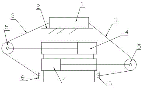
[0008] The invention includes a sliding table (1), a machine tool guide (2), and a machine tool body (6). The feature is that two identical hydraulic cylinders (4) are fixed side by side in opposite directions, and each hydraulic cylinder (4) ) Is connected with the rodless cavity of another hydraulic cylinder (4). A pulley (5) is installed on the piston rod of each hydraulic cylinder (4), and the sliding table (1) of the machine tool One end is fixed to one end of a steel wire rope (3). After the steel wire rope (3) passes through the pulley (5) on the side, the other end of the steel wire rope (3) is fixed to the machine tool body (6), which is fixed on the sliding table of the machine tool. The other end of (1) is fixed with another steel wire rope (3). After the steel wire rope (3) passes through the pulley (5) on one side, the other end of the steel wire rope (3) is fixed to the machine tool body (6).


PUM


Abstract

The invention discloses a driving device for a large-sized reciprocating motion machine tool. According to the driving device, two same hydraulic cylinders are fixed together in parallel in the opposite directions, a piston rod of each hydraulic cylinder is provided with a pulley, one end of a sliding workbench of the machine tool is fixedly connected with one end of one steel wire rope, and after the steel wire rope passes through the pulley on the edge where the steel wire rope is located, the other end of the steel wire rope is fixedly connected with a machine tool body; the other steel wire rope is fixed at the other end of the sliding workbench of the machine tool, and after the steel wire rope passes through the pulley on the edge where the steel wire rope is located, the other end of the steel wire rope is fixedly connected with the machine tool body. According to the driving device, in the strokes of the piston rods of the hydraulic cylinders, the sliding workbench can obtain the doubled stroke distance of the piston rods, the purpose of lowering costs can be achieved, in particular, the advantage of being easy to manufacture is achieved, and the sliding workbench with a large stroke of the machine tool can be driven.

Description

Technical field [0001] The invention relates to a driving device for a large-scale machine tool, in particular to a driving device for a large-scale reciprocating motion machine tool. Background technique [0002] At present, the gantry milling machines and gantry wound machines produced at home and abroad use hydraulic drive and screw drive. These two drive systems are almost impossible to grow when the machine length exceeds 6000mm, and the stroke of the hydraulic cylinder and the screw nut It is consistent with the stroke of the machine tool table. Therefore, if a large stroke machine tool is manufactured, the stroke of the hydraulic cylinder or screw nut of the driving mechanism must also be consistent with the stroke of the machine tool table. However, the hydraulic cylinder and the screw nut exceed A certain length limit is not only costly, but also more difficult to manufacture. Therefore, the machine tool with a length of 6000mm or more is basically a blank, but there are...

Claims


Application Information

Patent Timeline
Patent Type & Authority Applications(China)
IPC IPC(8): B23Q1/26
CPCB23Q1/26
Inventor 孙生强
Owner SUZHOU BLUE KING MACHINE TOOL TECH CO LTD
Why Eureka
Try Eureka