Air-pressing tool fixture and application thereof

A tooling and air pressure technology, applied in the field of tooling and fixtures, can solve the problems of contradicting the starting point of tooling design, increasing factors to be considered, and different pipe diameters, etc., and achieve the effect of shortening production cycle, convenient transportation and simple structure.

Inactive Publication Date: 2015-09-16
SHENYANG AIRCRAFT CORP
View PDF7 Cites 1 Cited by
  • Summary
  • Abstract
  • Description
  • Claims
  • Application Information

AI Technical Summary

Problems solved by technology

As for how to design this kind of fixture, there are currently three main problems: ① There are many types of parts, different pipe diameters, and different end forms, which results in more special-purpose tooling and less general-purpose tooling, which is different from tooling design. Contrary to the starting point
More factors are required to be considered in the design of tooling, which increases the difficulty of design
③ After the tooling is prepared, the repair and scrap rate during use is relatively high

Method used


Image

  • Air-pressing tool fixture and application thereof
  • Air-pressing tool fixture and application thereof
  • Air-pressing tool fixture and application thereof

Examples


Embodiment 1

[0021] Embodiment 1 A pneumatic fixture

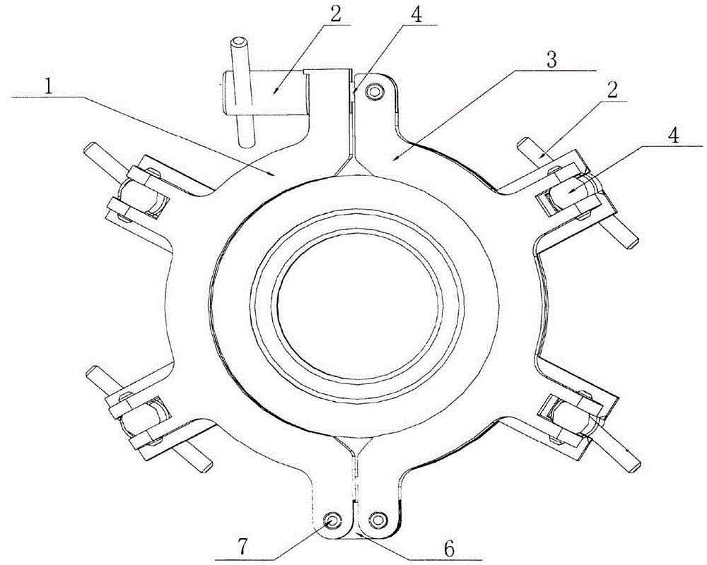
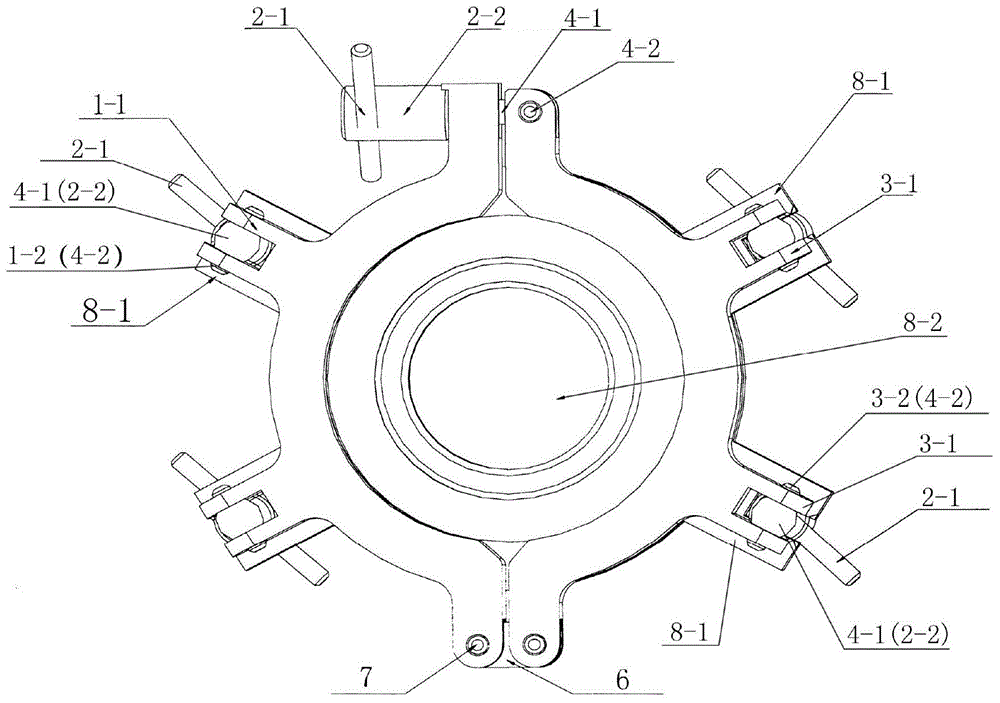
[0022] Such as Figure 1-Figure 3 As shown, a pneumatic tooling fixture: consists of a left supporting plate (1), a handle nut (2), a right supporting plate (3), a handle bolt (4), a connecting plate (6), a connecting bolt (7) and a blocking cover (8) Composition.

[0023] The left supporting plate (1) is provided with several connection parts I (1-1), the connection parts I (1-1) are U-shaped structures, and pin holes I (1-2) are provided at both ends.

[0024] The right supporting plate (3) is provided with several connection parts II (3-1), the connection part II (3-1) is a U-shaped structure, and pin holes II (3-2) are provided at both ends.

[0025] The handle nut (2) consists of a handle portion (2-1) and a nut portion (2-2).

[0026] One end of the handle bolt (4) is provided with a threaded portion (4-1), and the other end both sides are provided with a cylindrical pin (4-2).

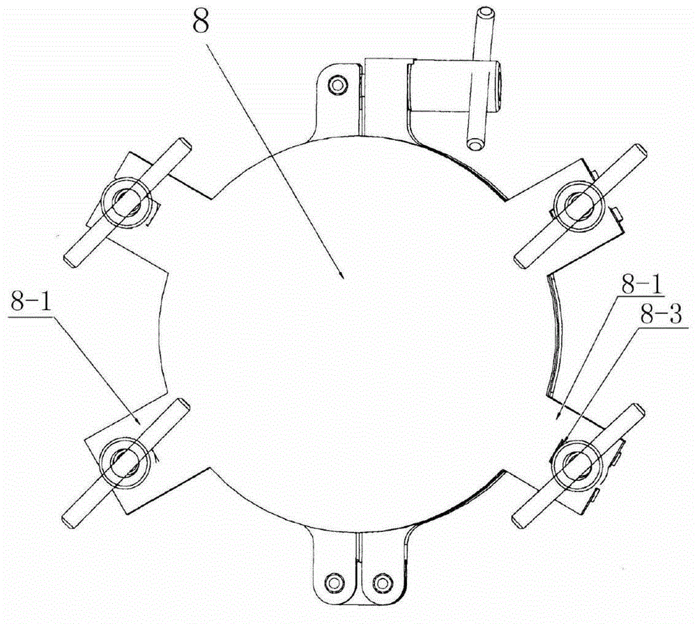
[0027] A connecting part III (8-1) correspondi...

Embodiment 2

[0034] Embodiment 2 The application of pneumatic fixtures in the strength and airtightness inspection of conduit parts.

[0035] The method is as follows: Fit the end of the catheter-like parts to be tested with the ring-shaped part positioning part (8-2) of the blocking cover (8), pass the handle nuts at the ends of the left supporting plate (1) and the right supporting plate (3) Cooperate with the handle bolts to tighten the left supporting plate (1) and the right supporting plate (3) to ensure the radial compression of the catheter parts to be tested; through the connecting part I (1-1) of the left supporting plate (1) and The fit between the handle nut and the handle bolt between the connecting part III (8-1) of the blocking cover, and the connecting part II (3-1) of the right support plate (3) and the connecting part III (8-1) of the blocking cover The cooperation between the handle nut and the handle bolt ensures the axial compression of the catheter parts to be tested. ...


PUM


Abstract

The invention relates to an air-pressing tool fixture and an application thereof. The air-pressing tool fixture is composed of a left support plate, a right support plate and a retaining cap; one end of the left support plate and one end of the right support plate are fixed with the retaining cap through connecting bolts, and the other end of the left support plate and the other end of the right support plate are connected with each other through matching of a handle nut and a handle bolt, the left support plate is provided with multiple connecting portions I, the right support is provided with multiple connecting portions II, the retaining cap is provided with connecting portions III corresponding to the connecting portions I and the connecting portions II, and the connecting portions I and the connecting portions II are connected with the connecting portions III through matching of handle nuts and handle bolts respectively. An annular part positioning portion is arranged in the middle of the retaining cap. According to the air-pressing tool fixture and the application thereof, the tool weight is light, the structure is simpler, operation and use are convenient, and the sealing performance can be guaranteed.

Description

technical field [0001] The invention belongs to the field of tooling fixtures, and in particular relates to a convenient and effective air pressure tooling fixture for checking the strength and airtightness of conduit parts without leakage and its application. Background technique [0002] Most of the cold process forming pipes and some hot process welding pipe fittings need to be inspected for strength and air tightness according to the technical requirements. The completion of this process mainly depends on the design and selection of fixtures. As for how to design this kind of fixture, there are currently three main problems: ① There are many types of parts, different pipe diameters, and different end forms, which results in more special-purpose tooling and less general-purpose tooling, which is different from tooling design. The starting point is contradictory. ② In the technical conditions of parts, the requirements for air pressure are different, and the requirements ...

Claims


Application Information

Patent Timeline
Patent Type & Authority Applications(China)
IPC IPC(8): B25B11/00G01N3/04
CPCB25B11/00G01N3/04
Inventor 马锡阁孙进鲍立峰
Owner SHENYANG AIRCRAFT CORP
Why Eureka
Try Eureka