

Air condensation structure
An air and air inlet technology, which is applied in the field of drying clothes, can solve the problems of uneven air intake in the air condensation structure, small contact area between steam and condenser, and high production cost of aluminum alloy materials, so as to improve heat exchange efficiency and increase contact Heat dissipation area and the effect of reducing the failure maintenance rate
- Summary
- Abstract
- Description
- Claims
- Application Information
AI Technical Summary
Problems solved by technology
Method used
Image

Examples
Embodiment Construction
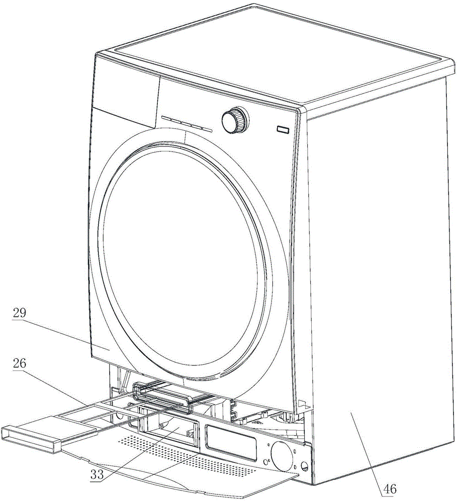
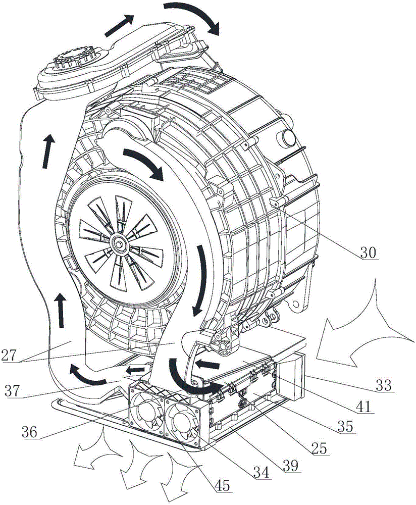
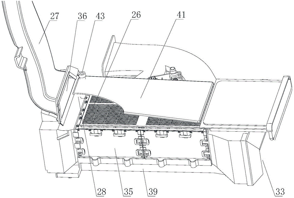
[0042] Such as image 3 As shown, a kind of air condensation structure of the present invention, described air condensation structure is a casing, comprises the air inlet 36 of hot air and the air outlet 37, also includes the air inlet 33 of cold wind and air outlet, the inside of air condensation structure A stacked heat exchanger is provided, and the heat exchanger is a plastic warp stacked in a criss-cross pattern, and a frame of a cage structure is arranged outside the heat exchanger.
[0043] Such as Figure 10 , Figure 11 , Figure 12 As shown, the stacked heat exchanger includes a plurality of stacked flaps 1, and the opposite sides of each flap 1 are bent upwards to cooperate with the upper flap 1 to form a ventilated air path. The adjacent flaps 1 are arranged vertically and horizontally alternately, forming horizontal wind passages and vertical wind passages which are mutually independent and spaced up and down. Among them, high-temperature air can be passed thr...
PUM
 Abstract
Description
Claims
Application Information