
Plugging device and processing and plugging construction method for reserved hole of cast-in-place slab pipeline

A plugging device and construction method technology, applied to building components, building insulation materials, etc., can solve the problems of uncompacted concrete, low construction work, high construction and maintenance costs, and achieve convenient processing, disassembly and assembly, and easy operation , The effect of low input cost

Inactive Publication Date: 2017-03-01
SHAANXI NO 8 CONSTR ENG
View PDF6 Cites 0 Cited by
  • Summary
  • Abstract
  • Description
  • Claims
  • Application Information

AI Technical Summary

Problems solved by technology

And nowadays, there is no uniform, standardized and specific construction method to follow when plugging the reserved pipe holes on the concrete cast-in-place slab. When the above-mentioned traditional construction methods are used for construction, it is inevitable that the construction operation is relatively random, There are many problems such as non-standard, cumbersome operation, slow construction speed, low construction workers, poor construction quality of reserved hole plugging, high construction and maintenance costs, unsatisfactory internal quality and visual effect of concrete, etc., and the construction quality is extremely vulnerable. The influence of factors such as the quality awareness, skill level, tools used, and construction environment of the operators will lead to the subsidence of the bottom mold of the reserved hole, grout leakage, loose concrete, water leakage around the pipeline, rust spots on the iron wire embedded in the concrete, and Common quality problems such as poor perception

Method used


Image

  • Plugging device and processing and plugging construction method for reserved hole of cast-in-place slab pipeline
  • Plugging device and processing and plugging construction method for reserved hole of cast-in-place slab pipeline
  • Plugging device and processing and plugging construction method for reserved hole of cast-in-place slab pipeline

Examples


Embodiment Construction

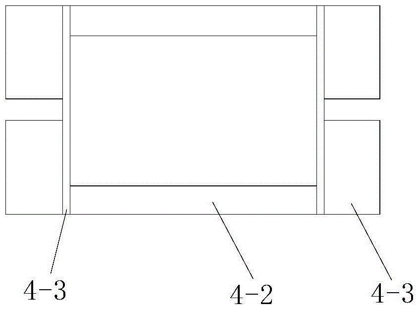
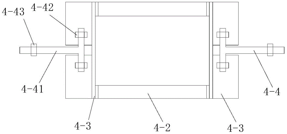
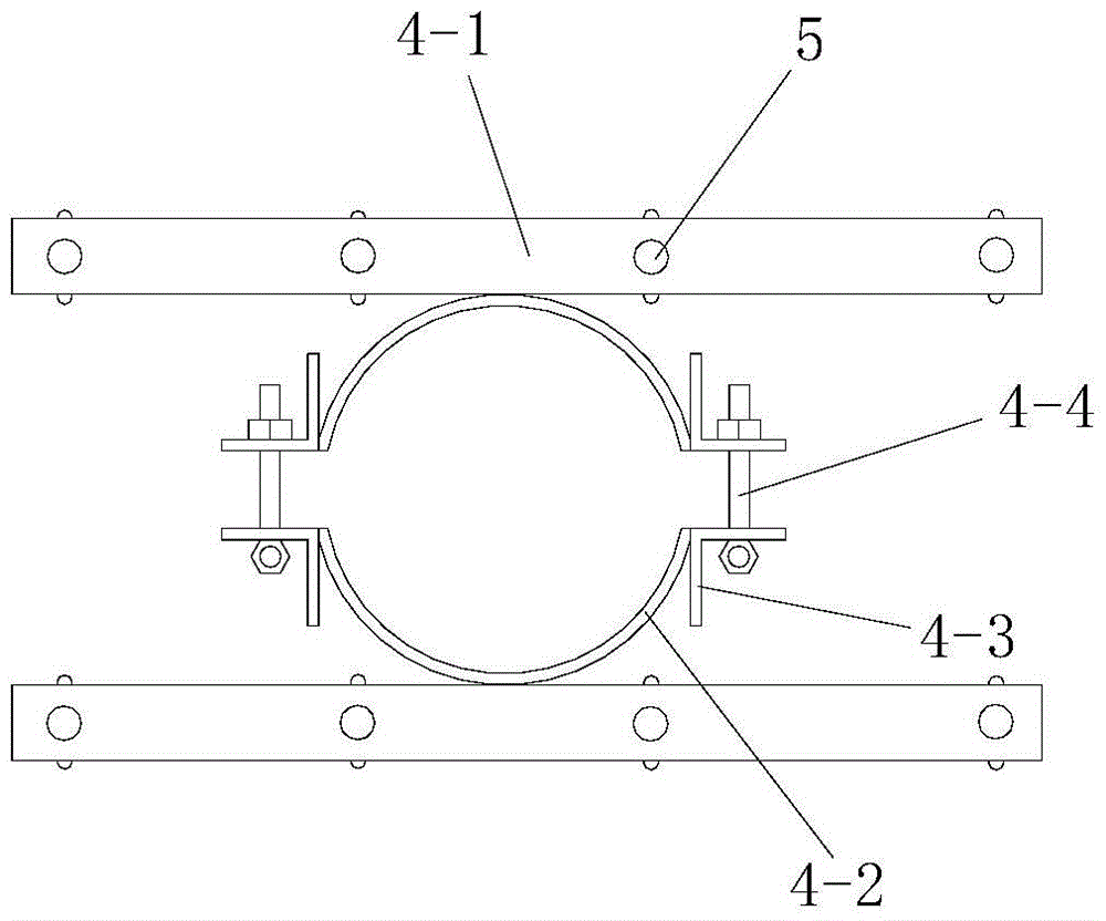
[0062] Such as image 3 , Figure 4 and Figure 7 A plugging device for a reserved hole in a cast-in-place slab pipeline is shown, including a plugging template 2 for plugging the bottom of the hole to be plugged between the pipeline 1 and the reserved hole and a template for stably supporting the plugging template 2 The supporting device 4, the reserved hole is the hole opened on the cast-in-place plate 3 for the installation of the pipeline 1 . The blocking formwork 2 is located below the cast-in-place slab 3 and is supported on the formwork supporting device 4. The blocking formwork 2 is a spliced ​​formwork formed by splicing a plurality of flat plates arranged on the same plane. A pipe installation hole for the installation of the pipe 1 is provided on the blocking template 2 . The template supporting device 4 is installed on the pipeline 1 and is located below the blocking template 2. The template supporting device 4 includes a hoop that is set on the pipeline 1 and c...


PUM


Abstract

The invention discloses a plugging device for a pipeline reserved hole of a cast-in-situ slab and a machining and plugging construction method. The plugging device comprises a plugging template and a template support device. The template support device is arranged on a pipeline and comprises a hoop and two support beams. Each support beam is provided with multiple top-propping parts. Each hoop comprises two semi-hoop bodies connected by means of connecting parts. Each semi-hoop body comprises an arc plate and two side reinforcing parts. The machining method for the plugging device comprises following steps of machining arc plates, machining side reinforcing parts, machining semi-hoop bodies, machining connecting parts, installing connecting parts and machining and installing support beams. The plugging construction method comprises following steps of processing a concrete interface, installing the template support device, splicing the plugging template, adjusting a support platform, synchronously moving the template support device and the plugging template upwards, pouring concrete, maintaining concrete and removing a mold. The plugging device is reasonably designed, easily and conveniently used and operated and conveniently constructed and has a good construction effect and is capable of effectively plugging the reserved hole.

Description

technical field [0001] The invention belongs to the technical field of plugging of reserved holes, and in particular relates to a plugging device for reserved holes of cast-in-place slab pipelines and a processing and plugging construction method. Background technique [0002] At present, in my country's housing construction projects, the plugging of the reserved pipe holes on the concrete cast-in-place plate basically still adopts the traditional construction method, and the plugging formwork is fixed with iron wire, square wood and short steel bars. And nowadays, there is no uniform, standardized and specific construction method to follow when plugging the reserved pipe holes on the concrete cast-in-place slab. When using the above-mentioned traditional construction methods, there will inevitably be relatively random construction operations, There are many problems such as non-standard, cumbersome operation, slow construction speed, low construction workers, poor construct...

Claims


Application Information

Patent Timeline
Patent Type & Authority Patents(China)
IPC IPC(8): E04B1/66
Inventor 刘鹏慧章辉张长虹刘小燕李天祥黄新刘鹏贾锋贤陈康安
Owner SHAANXI NO 8 CONSTR ENG
Learn More