Variable bent joint
A bendable and variable technology, applied in wellbore/well components, earth-moving drilling, etc., can solve the problems of low reuse rate and high cost of salvage tools, and achieve high salvage success rate, wide application range and high strength. Effect
- Summary
- Abstract
- Description
- Claims
- Application Information
AI Technical Summary
Problems solved by technology
Method used
Image
Examples
Embodiment Construction
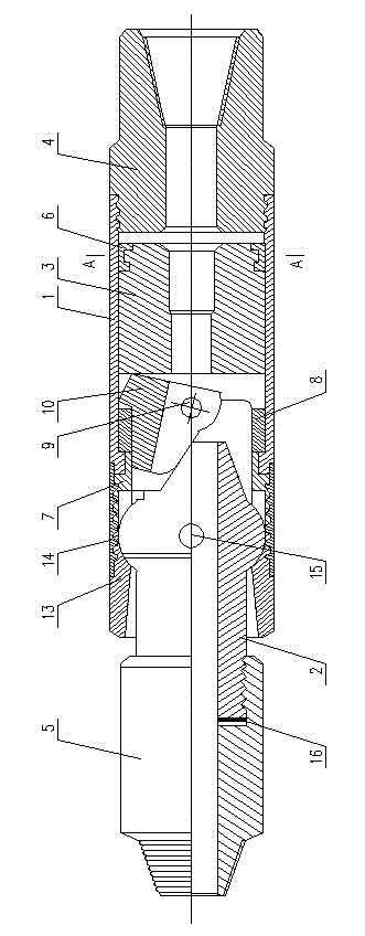
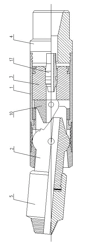
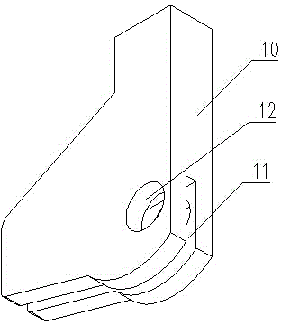
[0017] The bendable joint includes an outer cylinder 1 , an orientation joint 2 , a piston 3 , an upper joint 4 and a lower joint 5 . One end of the outer cylinder 1 is threaded with an upper joint 4 ; a piston 3 is installed in the outer cylinder 1 on one side of the upper joint 4 through a piston ring 6 . The piston ring 6 is a three-lobe ring, and the piston ring 6 is sleeved on the piston 3 . The other end of the outer cylinder 1 is screwed with an upper ball seat 7 , and a cam 10 is installed in the outer cylinder 1 between the upper ball seat 7 and the piston 3 by a cam seat 8 and a cam pin 9 . The cam 10 can rotate around the cam pin 9 to a certain extent. The cam 10 is flat and convex. The bottom of the cam 10 is provided with an assembly groove 11 , and the assembly groove 11 is provided with a cam pin hole 12 .
[0018] One side of the upper ball seat 7 is provided with a lower ball seat 13, and the upper ball seat 7 and the lower ball seat 13 are threadedly connect...
PUM
 Abstract
Description
Claims
Application Information
 - R&D
- Intellectual Property
- Life Sciences
- Materials
- Tech Scout
- Unparalleled Data Quality
- Higher Quality Content
- 60% Fewer Hallucinations
Browse by: Latest US Patents, China's latest patents, Technical Efficacy Thesaurus, Application Domain, Technology Topic, Popular Technical Reports.
© 2025 PatSnap. All rights reserved.Legal|Privacy policy|Modern Slavery Act Transparency Statement|Sitemap|About US| Contact US: help@patsnap.com


