New method for leakage detection of Freon valve

A freon and new method technology, applied in the field of valve supervision and inspection, can solve the problems of insufficient precision, short time consumption, high detection cost, etc., and achieve the effects of ensuring detection accuracy, increasing pressure and reducing pollution

Active Publication Date: 2015-09-16
温州市特种设备检测研究院 +1
View PDF8 Cites 12 Cited by
  • Summary
  • Abstract
  • Description
  • Claims
  • Application Information

AI Technical Summary

Problems solved by technology

Although the traditional bubble leak detection method can detect the leakage, it cannot measure the leakage amount. Although the improved gas collection method can measure the leakage amount, the accuracy is not enough, and the implementation limitations are very large
The pressure drop leak detection method can indirectly calculate the leak rate, but it is difficult to detect small leaks due to detection and accuracy reasons, and the efficiency is low in general industrial sites
The sensor flow detection method can directly detect the leakage rate, but the accuracy of the instrument required for micro-leakage measurement is very high, resulting in high detection costs, which is difficult to achieve in general industrial sites
The helium gas spectroscopic analysis detection method mainly detects micro-leakage, and the leak detection sensitivity is high, but it needs to create a vacuum environment, the whole detection process takes a long time, and helium is expensive, the detection cost is high, and the utilization rate in valve enterprises is low
The ultrasonic leak detection method can quickly locate the leak point, takes a short time, and has high leak detection accuracy. However, the development of ultrasonic leak detection equipment is difficult. At present, ultrasonic leak detectors at home and abroad can only make qualitative judgments and cannot calculate the amount of leakage.
The traditional halogen detection method uses a large amount of freon, which is easy to cause great pollution to the environment

Method used


Image

  • New method for leakage detection of Freon valve

Examples


Embodiment Construction

[0010] The specific embodiments of the present invention will be described in detail below in conjunction with the technical solutions and accompanying drawings.

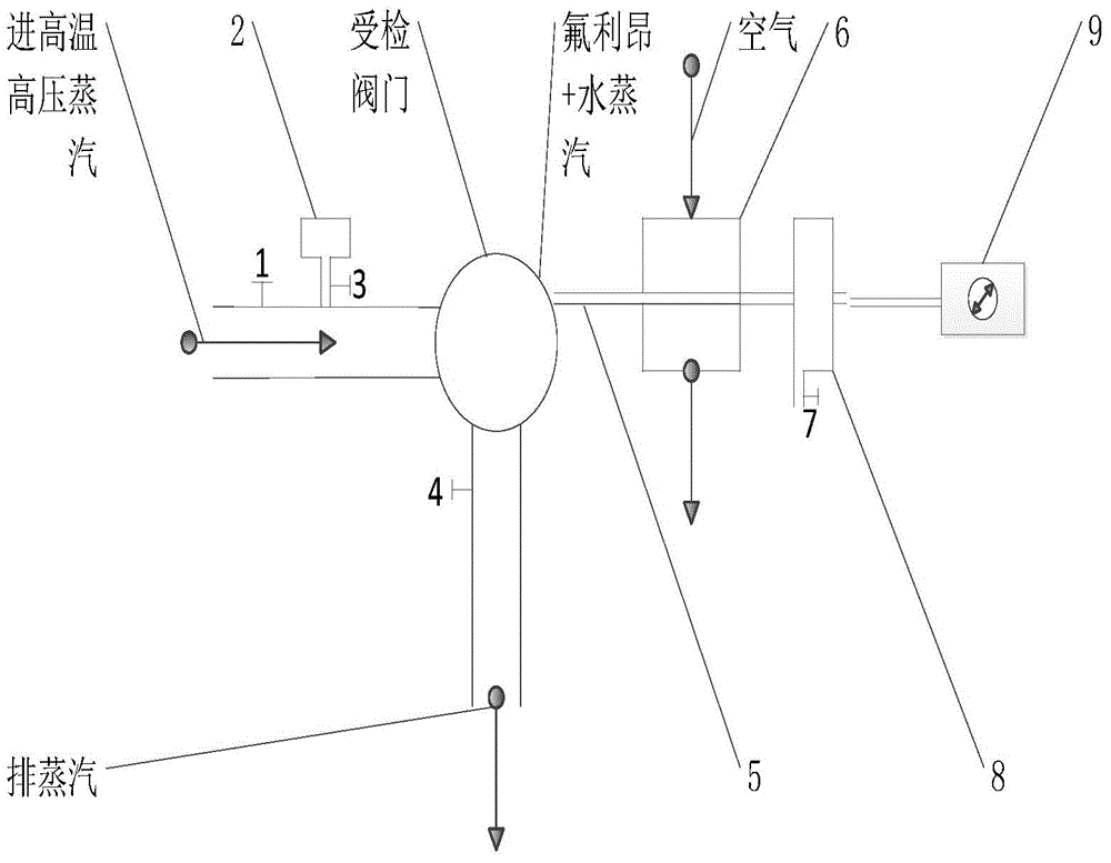
[0011] The working process of the present invention is as follows: arrange according to the schematic diagram of the device, align the probe of the halogen detector 9 with the outlet of the gas-liquid separation device 8, and because the gas density of Freon is higher than that of air, the probe of the halogen detector 9 should be close to the gas-liquid separation device 8 The lower edge of the gas outlet, the horizontal distance between the probe of the halogen detector 9 and the gas outlet of the gas-liquid separation device 8 is not more than 3mm. Open the high-temperature and high-pressure steam control valve 1, the exhaust steam valve 4 and the inspected valve, and close the Freon control valve 3 at the same time, and pass the high-temperature and high-pressure steam into the high-temperature and high-pressure ...


PUM


Abstract

The invention provides a new method for leakage detection of a Freon valve, and belongs to the technical field of valve supervision and inspection. Freon is input via a Freon control vale firstly, high-temperature high-voltage water vapor is input via a high-temperature high-voltage stream control valve then, a mixed gas of the high-temperature high-voltage water vapor and the Freon enters a checked valve, multipoint step-by-step air extraction is performed on the checked valve by using an air extracting device, the extracted mixed gas is cooled in an air cooling device firstly, gas-liquid separation is performed in a gas-liquid separation device subsequently, and, finally, a halogen detector performs detection at air outlet of the gas-liquid separation device. The usage amount of the Freon is reduced, and serious pollution caused by that total fluoride as a working medium performs detection is reduced; a leakage point is accurately located through detection for the tracer gas Freon, and the leakage grade is determined through the number of lit alarm indicating lamps; and the cooling and gas-liquid separation devices are increased, an influence of too high stream temperature is prevented, and inspection precision is improved.

Description

technical field [0001] The invention belongs to the technical field of valve supervision and inspection, and in particular uses freon as a tracer gas to detect valve leakage points and determine leakage levels. Background technique [0002] At present, the valve leak detection methods mainly include: bubble leak detection method, halogen leak detection method, pressure drop leak detection method, sensor flow detection method, helium gas spectral analysis detection method and ultrasonic leak detection method. Although the traditional air bubble leak detection method can detect the leakage, it cannot measure the leakage amount. Although the improved gas collection method can measure the leakage amount, the accuracy is not enough, and the implementation limitations are very large. The pressure drop leak detection method can indirectly calculate the leakage rate, but it is difficult to detect small leaks due to detection and accuracy reasons, and the implementation efficiency in...

Claims


Application Information

Patent Timeline
Patent Type & Authority Applications(China)
IPC IPC(8): G01M3/22
Inventor 金樟民沈志斌张奇张博李敏张海
Owner 温州市特种设备检测研究院
Why Eureka
Try Eureka