Cervical vertebra anterior distraction device suitable for minimally invasive surgery

An anterior cervical, minimally invasive surgery technology, applied in surgery, medical science and other directions, to achieve the effect of good vision

Inactive Publication Date: 2015-09-23
陈远明
View PDF6 Cites 18 Cited by
  • Summary
  • Abstract
  • Description
  • Claims
  • Application Information

AI Technical Summary

Problems solved by technology

But, when described bone expander is used for minimally invasive surgery, still there is the defective of above-mentioned prior art

Method used


Image

  • Cervical vertebra anterior distraction device suitable for minimally invasive surgery
  • Cervical vertebra anterior distraction device suitable for minimally invasive surgery
  • Cervical vertebra anterior distraction device suitable for minimally invasive surgery

Examples


example 1

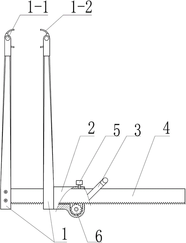
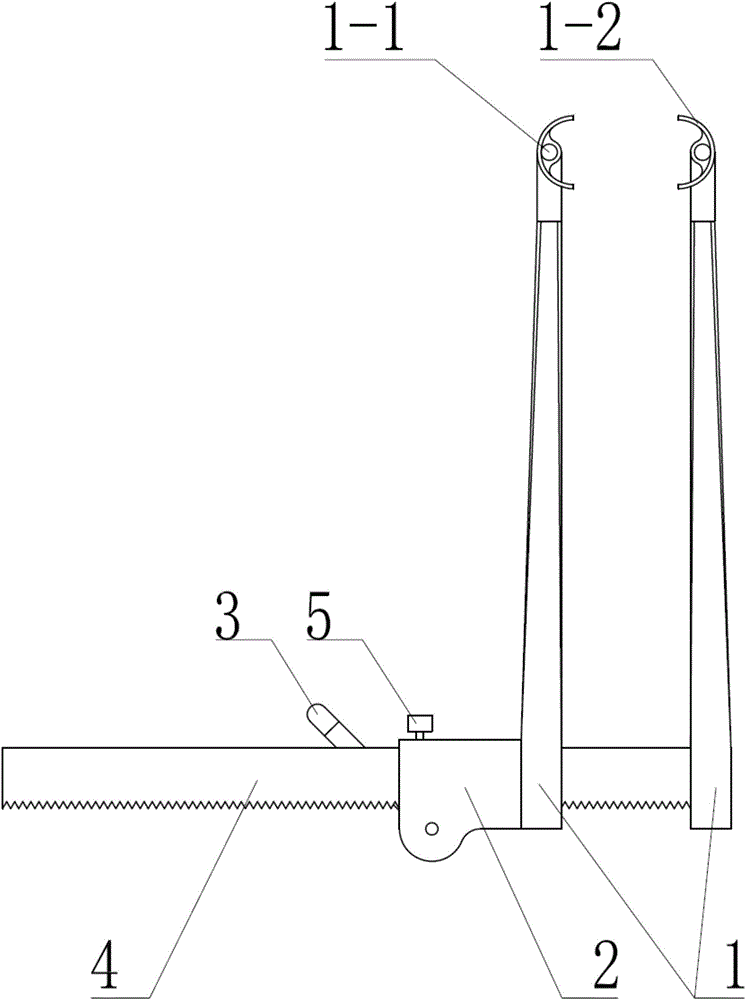
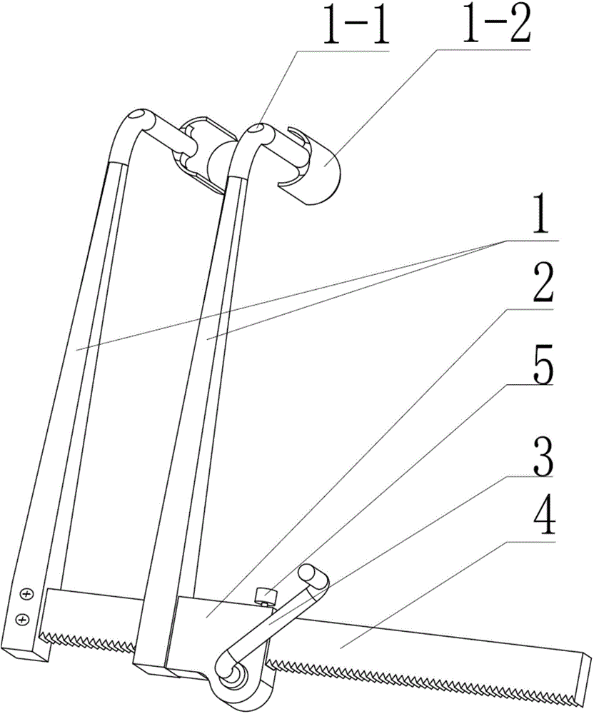
[0019] see Figure 1~3 , the anterior cervical spreader in this example includes two tubular pin seats 1 interconnected by a parallel guiding device, wherein the parallel guiding device is a rack and pinion transmission mechanism, and the mechanism is composed of mutually meshing gears 6 , a rack 4, a guide sleeve 2 that is set on the rack 4 and accommodates the gear 6 therein, a handle 3 that manipulates the rotation of the gear 6, and a set screw 5 that is passed through the guide sleeve 2 composition.

[0020] see Figure 1~3 , the two tubular pin seats 1, one is fixed on the rack 4, the other is fixed on the guide sleeve 2, and each tubular pin seat 1 has a needle connected with the vertebra to be stretched The circular pinhole 1-1; the lower end of the tubular pin seat 1 is provided with an arc-shaped baffle 1-2, and the arc radius of the inner circular surface of the arc-shaped baffle 1-2 is larger than the circular arc radius The radius of the pinhole 1-1, and the in...

example 2

[0022] Compared with Example 1, this example has two improvements. One is to improve the mechanism that restricts the reverse rotation of the gear, which is formed by setting the positioning screw on the back of the rack, to a one-way limit device composed of a pawl and a compression spring. The second is to improve the lower end of the arc-shaped baffle into an upwardly arched arc profile. Among them, the first improved scheme such as Figure 4 As shown, the second improved scheme is as Figure 5 with Image 6 shown.

[0023] see Figure 4 , the one-way limiting device includes a pawl 11, the pawl 11 is hinged on the guide sleeve 2 on one side of the gear 6, and one end extends into the rack 4 between the hinge point and the tubular pin seat 1 In the alveolar, a compression spring 12 is arranged between the other end and the guide sleeve 2 .

[0024] see Figure 5 with Image 6 , the lower end of the arc-shaped baffle plate 1-2 arranged at the lower end of the tubular ...


PUM


Abstract

The invention relates to a cervical vertebra anterior distraction device suitable for minimally invasive surgery. The cervical vertebra anterior distraction device suitable for minimally invasive surgery comprises two tubular pin seats which are connected through a parallel guiding device. The parallel guiding device is a gear and track transmission mechanism which is composed of a gear, a rack, a guiding sleeve and a handle which are meshed. One of the two tubular pin seats is fixed to the rack, and the other tubular pin seat is fixed to a guiding sleeve. Each tubular pin seat is provided with a round needle hole penetrating through a needle connected with the vertebra to be distracted, wherein the lower end of the tubular pin seat is provided with a circular arc baffle, the radius of the circular arc of the inner circular face of the circular arc baffle is larger than that of the round needle hole, and the inner circular face of the circular arc baffle and the inner surface of the round needle hole are in projection tangency in the plane perpendicular to the axis of the round needle hole. The openings of the circular arc baffles at the lower ends of the two tubular pin seats are opposite.

Description

technical field [0001] The invention relates to a surgical instrument, in particular to an instrument for keeping a wound open. Background technique [0002] The anterior cervical spreader is a medical device commonly used in anterior cervical surgery. Its function is to spread the soft tissues such as skin and muscles and the two vertebral bodies during the operation, so as to expand the soft tissues such as skin and muscles and the intervertebral space, which is convenient. Surgery is performed. However, since the cervical vertebrae belong to the deeper tissues of the human body, and human muscles have good elasticity, after the cervical vertebrae are opened with a spreader in minimally invasive surgery, the muscles will still block the doctor's field of vision. The method for solving the above problems in the prior art is that several assistants use pull hooks to pull the skin and muscles around the wound outwards, which not only wastes human resources, but also increase...

Claims


Application Information

Patent Timeline
Patent Type & Authority Applications(China)
IPC IPC(8): A61B17/02A61B17/56
CPCA61B17/00234A61B17/0206A61B17/0218A61B17/025A61B2017/0256A61B2017/564
Inventor 陈远明
Owner 陈远明
Why Eureka
Try Eureka