Medical rotary cutter control system

A technology of control system and rotary cutter, which is applied in the field of medical equipment, can solve the problems of increasing the probability of injury to the human body by the rotary cutter head, the extraction time is not fixed, and staying in the pipeline, etc. It is easy to promote and use, simple in structure, The effect of avoiding harm

Active Publication Date: 2015-09-23
苏州迈迪诺生命科技有限公司
View PDF8 Cites 11 Cited by
  • Summary
  • Abstract
  • Description
  • Claims
  • Application Information

AI Technical Summary

Problems solved by technology

[0003] When the tissue sample is rotary cut, in the process of being pumped into the sample chamber, in order to ensure that the sample chamber has a suitable negative pressure, a power source is required to drive the vacuum pump to continue to work, and the rotary cutter rotates synchronously. At this time, the rotary cutter The head of the knife often causes damage to the surrounding human tissues, such as burns to the human body due to rotational friction or heat, especially in the process of sample extraction, due to the hardness and The viscosities are different, and the moving speed of the tissue samples in the rotary cutting tube is also different, which leads to the unfixed sampling time, and it is difficult to accurately control the time when the sampling tissue reaches the sampling room. If the extraction time is short, it will be If the sampled tissue stays in the pipeline, if the extraction time is too long, the chance of harming the human body by the rotary cutter head will be greatly increased. Therefore, it is necessary to improve the power control system of the existing medical rotary cutter

Method used


Image

  • Medical rotary cutter control system
  • Medical rotary cutter control system
  • Medical rotary cutter control system

Examples


Embodiment Construction

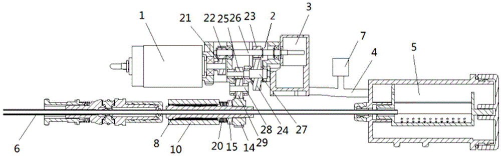
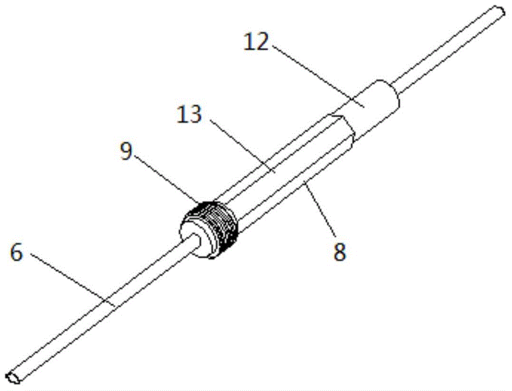
[0029] see Figure 1-2 , a medical rotary cutter control system, which includes a motor 1, the output end of the motor 1 is provided with a splitter 2 for dividing the output power of the motor 1 into two transmissions, wherein the first transmission drives a vacuum pump 3 rotation, the suction end of the vacuum pump 3 communicates with the sample chamber 5 through the pipeline 4, the second transmission drives the rotary cutter tube 6 to rotate, and the rotary cutter tube 6 is set to cooperate with the second transmission and A clutch device suitable for cutting off the transmission when the rotary cutter tube 6 has been rotary-cut. The medical rotary cutter control system of this embodiment sets a clutch device between the second transmission and the rotary cutter. The transmission is disconnected under the action of the vacuum pump. At this time, the power of the second transmission cannot be transmitted to the rotary cutter tube, and the rotary cutter head is in a static ...


PUM


Abstract

The invention discloses a medical rotary cutter control system. The system comprises a motor, wherein a branching unit used for dividing the output power of the motor into two driving paths is arranged at the output end of the motor, the first driving path drives a vacuum pump to rotate, the air suction end of the vacuum pump is communicated with a sample room through a pipeline, the second driving path drives a rotary cutter tube to rotate, and a clutch device which is in normal-running fit with the second driving path and can release the drive when rotary cutting is completed by the rotary cutter tube is arranged on the rotary cutter tube. By the adoption of the system, the advantages of the single-power scheme that size is small and power consumption is low are reserved, and the defects that in the prior art, a rotary cutter has to work synchronously with a vacuum pump, and harm is caused to people are overcome. Furthermore, the system is simple in structure, low in manufacturing cost and convenient to use and popularize.

Description

technical field [0001] The invention relates to the technical field of medical instruments, in particular to a control system for a medical rotary cutter. Background technique [0002] Due to the limitation of volume and power consumption, portable (handheld) medical vacuum rotary cutting system usually chooses a single power scheme, that is, a single motor or similar power source drives the rotary cutter and vacuum pump to cut and extract tissue samples . Because the rotary cutter and the vacuum pump in the prior art all move synchronously, this has just produced a clinical problem: [0003] When the tissue sample is rotary cut, in the process of being pumped into the sample chamber, in order to ensure that the sample chamber has a suitable negative pressure, a power source is required to drive the vacuum pump to continue to work, and the rotary cutter rotates synchronously. At this time, the rotary cutter The head of the knife often causes damage to the surrounding human...

Claims


Application Information

Patent Timeline
Patent Type & Authority Applications(China)
IPC IPC(8): A61B17/3209A61B10/02
CPCA61B10/02A61B17/3209A61B2017/00017
Inventor 陆鉴良方志庆沈超
Owner 苏州迈迪诺生命科技有限公司
Why Eureka
Try Eureka