Method and device for achieving full-profile grinding of blades with tenons through cylindrical coordinate three-axis linkage machine tool

A technology of cylindrical coordinates and three-axis linkage, which is applied in the direction of grinding drive devices, grinding machine parts, grinding workpiece supports, etc., can solve the problems of unfavorable blade working strength, reduced blade processing cost, and small blade geometric size. Achieve the effects of improving machine tool production efficiency, reducing plant size, reducing requirements and equipment costs

Active Publication Date: 2015-09-23
枣庄北航机床创新研究院有限公司
View PDF9 Cites 9 Cited by
  • Summary
  • Abstract
  • Description
  • Claims
  • Application Information

AI Technical Summary

Problems solved by technology

The machining process of this kind of processing method needs to change the tool, which will cause the knife connection mark at the knife joint, which is not conducive to improving the working strength of the blade, and the positioning error will occur when the tenon of the blade is transferred to different machine tools for processing
In addition, the machine tools for machining these surfaces usually require 4 to 5 axes of motion, and it is almost impossible to use a three-axis linkage machine tool for machining, which limits the reduction of blade machining costs, and the geometric size of the blade is small, and the structural size of the machine tool is large , the consumption of energy and plant is also very significant

Method used


Image

  • Method and device for achieving full-profile grinding of blades with tenons through cylindrical coordinate three-axis linkage machine tool
  • Method and device for achieving full-profile grinding of blades with tenons through cylindrical coordinate three-axis linkage machine tool
  • Method and device for achieving full-profile grinding of blades with tenons through cylindrical coordinate three-axis linkage machine tool

Examples


Embodiment Construction

[0039] See figure 1 — Figure 9 , the embodiment of the present invention is described below in conjunction with accompanying drawing.

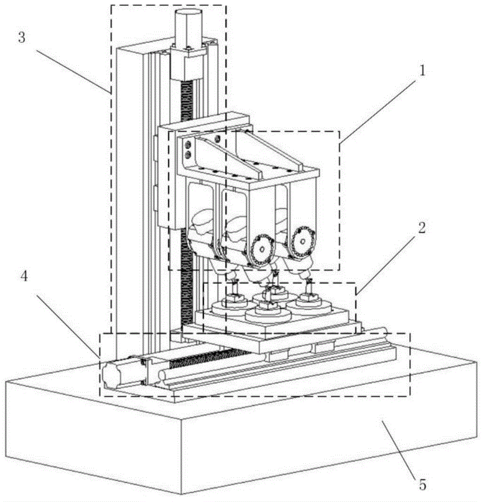
[0040] Such as Figure 5 As shown, the four blades 2-4 are installed on the four fixtures 2-3 of the CNC machine tool in an array with the tenons facing upwards, so as to ensure that the length direction of the blade body of the blades 2-4 is consistent with that of the rotary table 2-2 or the rotary shaft. The direction of the axis is basically the same, especially to ensure that the mortise edge plate is as parallel as possible to the horizontal plane. The fixture 2-3 array is installed on the workbench 2-2, and the turntable is driven by the same motor, which can realize synchronous rotation.

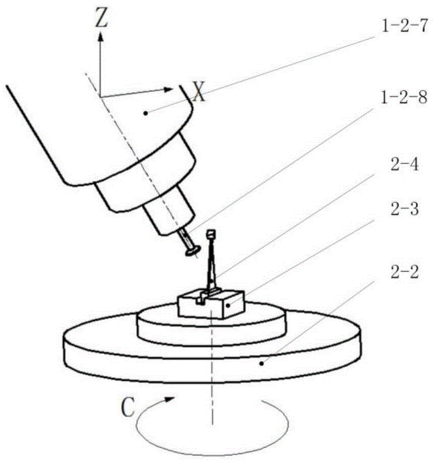
[0041] Such as Figure 4 Combined with the structural form of the blade 2-4 as shown, select a suitable disc-shaped grinding wheel 1-2-8 whose rod diameter is smaller than the diameter of the grinding wheel and install it on the main shaft 1-2-7...


PUM


Abstract

The invention discloses a method and device for achieving full-profile grinding of blades with tenons through a cylindrical coordinate three-axis linkage machine tool. The device is characterized in that the blades are mounted on a rotating shaft of a numerical control machine tool in a manner that the tenons are arranged upwards, and the three-axis linkage machine tool is formed by other two linear shafts of the numerical control machine tool and the rotating shaft; the three-axis linkage machine tool is used for driving a disc grinding wheel to carry out full-profile grinding machining on the blades; a rotating shaft of the grinding wheel is not parallel to or perpendicular to a rotating working table of the machine tool or the axis of the rotating shaft, the phenomenon that the length of the grinding wheel is shortened is avoided, and the long blades are machined; according to the method, only through three motion axes, the tenons and profiles of the blades can be comprehensively machined; the machine tool manufactured through the method has the coat far below a five-axis linkage numerical control machine tool, and a square matrix structure is formed through a plurality of spindles and the rotating shaft, so that multiple blade parts can be machined on the same machine tool, and the production efficiency of the machine tool can be obviously improved.

Description

technical field [0001] The invention relates to a full-profile grinding method and device for a blade with an edge plate and a tenon at one end, in particular to a method and a device for realizing full-profile grinding of a blade with a tenon by using a cylindrical coordinate three-axis linkage machine tool, belonging to The technical field of blade machining. Background technique [0002] At present, the tenon, edge plate and airfoil of blades with complex profiles are usually milled on a five-axis machine tool with A-axis and B-axis, and the middle part of the airfoil is usually milled with a high-efficiency belt round Corner end milling is used for milling, while the edge plate and the part near the edge plate on the blade body are basically milled with a ball-end cutter, and the tenon part is usually shaped and ground on a slow-feed grinder. The machining process of this processing method needs to change the tool, which will cause the knife connection mark at the knife...

Claims


Application Information

Patent Timeline
Patent Type & Authority Applications(China)
IPC IPC(8): B24B19/14B24B27/00B24B47/12B24B41/06B24B1/00
CPCB24B1/00B24B19/14B24B27/0023B24B27/0061B24B41/06B24B47/12
Inventor 陈志同崔伟宁涛李勋张云
Owner 枣庄北航机床创新研究院有限公司
Why Eureka
Try Eureka