Yarn winder and winding method

A yarn winding machine and yarn technology, which is applied in the direction of conveying filamentous materials, thin material processing, transportation and packaging, etc., can solve the problems of difficult handling and larger package size, and achieve increased winding density, The effect of suppressing the increase in package size and easy handling

Active Publication Date: 2015-09-23
MURATA MASCH LTD
View PDF18 Cites 5 Cited by
  • Summary
  • Abstract
  • Description
  • Claims
  • Application Information

AI Technical Summary

Problems solved by technology

As a result, there are problems such as large package size and difficult handling

Method used


Image

  • Yarn winder and winding method
  • Yarn winder and winding method
  • Yarn winder and winding method

Examples


Embodiment Construction

[0036] Next, embodiments of the present invention will be described with reference to the drawings. In addition, in this specification, "upstream" and "downstream" mean upstream and downstream in the traveling direction of the yarn at the time of yarn winding.

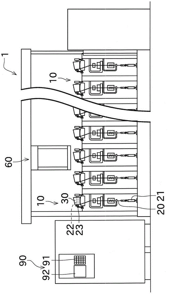
[0037] Such as figure 1 As shown, an automatic winder (yarn winding machine) 1 includes a plurality of yarn winding units 10, a doffing device 60, and a machine control device 90 arranged side by side.

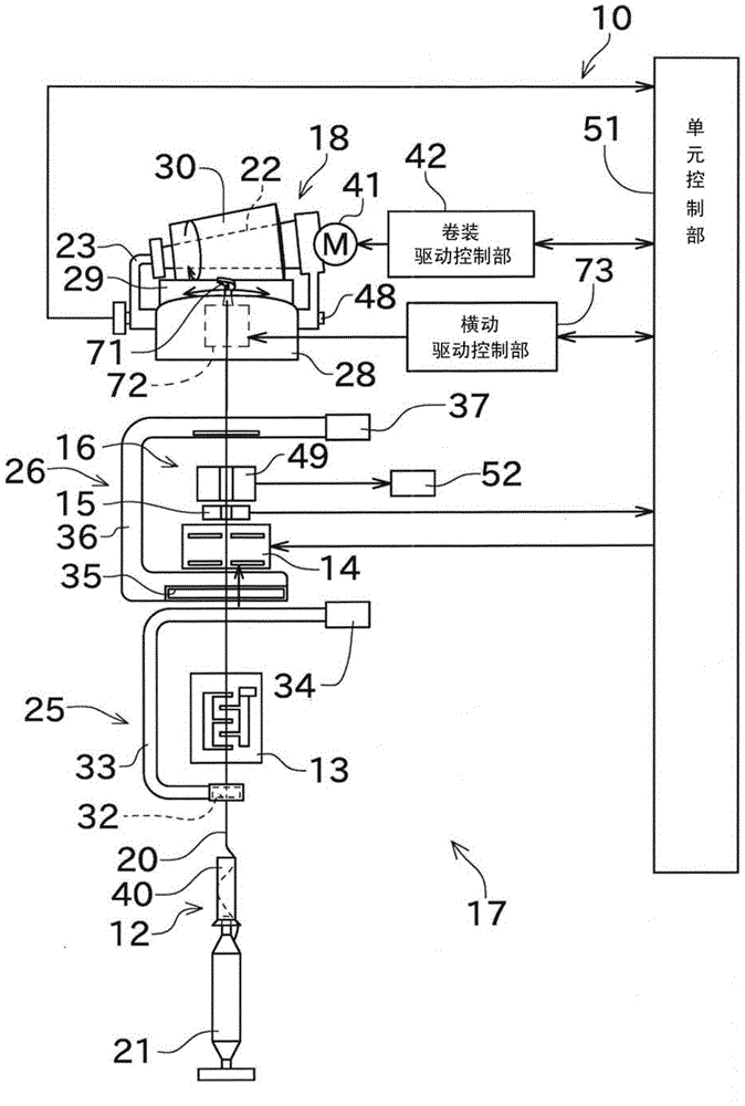
[0038] Each yarn winding unit 10 winds the yarn 20 unwound from the yarn supply bobbin 21 on the tapered winding bobbin 22 supported by the cradle 23 while traversing the yarn 20 to form a package 30 . Furthermore, the cradle 23 has a small-diameter side support portion for rotatably supporting the small-diameter side end portion of the winding tube 22 , and a large-diameter side support portion for rotatably supporting the large-diameter side end portion of the winding tube 22 .

[0039] The doffing device 60 advanc...


PUM


Abstract

The invention provides a yarn winder and a winding method. An automatic winder (1) includes a cross arm (71) and a unit control section (51). The cross arm (71) makes yarn (20) winding on a conical winding device (30) move transversely. During the winding, the unit control section (51) makes the transverse moving speed of the cross arm (71) in a small-diameter side area increase relative to the transverse moving speed ratio, namely the transverse moving speed ratio, of the cross arm (71) in a large-diameter side area.

Description

technical field [0001] The present invention relates to a yarn winding machine that winds a yarn while traversing the yarn to form a cone-shaped package. Background technique [0002] Conventionally, in a yarn winding machine for winding a conical package, control is performed such that the traverse speed in the large diameter side region of the package is lower than the traverse speed in the small diameter side region. By performing this control, the shape of the package can be formed appropriately, and the winding density in the large-diameter side region can be increased, so that the unwinding property of the package can be improved. In the following description, the ratio of the traverse speed in the small-diameter region to the traverse speed in the large-diameter region is referred to as the traverse speed ratio. German Patent Application Publication No. 102008015907 (Patent Document 1) and Japanese Patent Laid-Open No. 2012-017205 (Patent Document 2) disclose a yarn ...

Claims


Application Information

Patent Timeline
Patent Type & Authority Applications(China)
IPC IPC(8): B65H54/28
CPCB65H54/103B65H54/2827B65H54/2884B65H2701/31
Inventor 牟田胜文
Owner MURATA MASCH LTD
Why Eureka
Try Eureka