Check patentability & draft patents in minutes with Patsnap Eureka AI!

A foundation pit support pressure detection device

A detection device and foundation pit support technology, which is applied in basic structure engineering, basic structure testing, excavation, etc., can solve problems such as the inability of pressure monitoring, and achieve the advantages of saving manpower, reasonable mechanism design, and increasing supporting force. Effect

Active Publication Date: 2016-09-28
ZHEJIANG OCEAN UNIV
View PDF5 Cites 0 Cited by
  • Summary
  • Abstract
  • Description
  • Claims
  • Application Information

AI Technical Summary

Problems solved by technology

[0004] The present invention aims at the above shortcomings, and is based on solving the problem that the existing foundation pit horizontal support device cannot achieve real-time pressure monitoring

Method used


Image

  • A foundation pit support pressure detection device
  • A foundation pit support pressure detection device

Examples


Embodiment 1

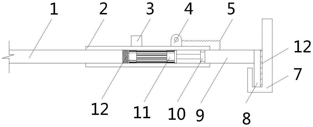
[0017] A pressure detection device for foundation pit support, comprising a clamping slot 7, a clamping plate 8 embedded in the clamping slot 7, a pressure monitoring device 9 is connected to the clamping plate 8, and a top block is arranged behind the pressure monitoring device 9 10. The hydraulic rod 11 is pushed behind the top block 10, the beam 1 is connected behind the hydraulic rod 11, and the controller 3 is connected to the periphery of the hydraulic rod 11 to control the entire device.

[0018] In order to protect the structure of the hydraulic rod 11 from being crushed during the elongation process, a rubber pad 12 is sandwiched between the beam 1 and the hydraulic rod 11 , and between the slot 7 and the clamping plate 8 . During the working process of the device, in order to ensure that the device is not damaged, a sleeve 2 is sheathed on the periphery of the hydraulic rod 11 , and the sleeve 2 extends to the top of the beam 1 and the top of the pressure monitoring d...


PUM


Abstract

A foundation pit support pressure detection device comprises a clamping groove and a clamping plate embedded in the clamping groove. The foundation pit support pressure detection device is characterized in that the clamping plate is connected with a pressure monitor device; an ejector block is arranged behind the pressure monitor device; a hydraulic rod abuts against the rear portion of the ejector block; a cross beam is connected with the rear portion of the hydraulic rod; and a controller is connected with the periphery of the hydraulic rod. Compared with the prior art, the foundation pit support pressure detection device has the following advantages that through the spliced structural design, a pressure sensor and a hydraulic cylinder are arranged, pressure can be monitored and raised in real time, supporting force is increased, and a foundation pit is prevented from collapsing. The foundation pit support pressure detection device is reasonable in structural design, saves manpower and is suitable for being used and popularized.

Description

technical field [0001] The invention belongs to the technical field of foundation pit support, and in particular relates to a foundation pit support pressure detection device. Background technique [0002] The foundation pit is an earth pit excavated at the foundation design position according to the base level and foundation plane size. Before excavation, the excavation plan should be determined according to the geological and hydrological data, combined with the conditions of the nearby buildings, and the waterproof and drainage work should be done well. If the excavation is not deep, the side slope can be used to stabilize the soil slope, and the slope size is determined according to the relevant construction regulations. For those with deep excavation and nearby buildings, the foundation pit wall support method, shotcrete retaining wall method, and large foundation pit even adopt methods such as underground diaphragm wall and column-type bored pile interlocking to preve...

Claims


Application Information

Patent Timeline
Patent Type & Authority Patents(China)
IPC IPC(8): E02D33/00E02D17/04
Inventor 田美灵王晋宝
Owner ZHEJIANG OCEAN UNIV
Features
  • R&D
  • Intellectual Property
  • Life Sciences
  • Materials
  • Tech Scout
  • Unparalleled Data Quality
  • Higher Quality Content
  • 60% Fewer Hallucinations
Learn More