Direct-current residual current detection apparatus

A residual current and detection device technology, applied in the direction of measuring devices, circuit devices, emergency protection circuit devices, etc., can solve the problems of increased power consumption, increased circuit cost, complex structure, etc., and achieve reliable work, easy implementation, and simple structure Effect

Active Publication Date: 2015-09-23
SEARI ELECTRIC TECH +1
View PDF7 Cites 24 Cited by
  • Summary
  • Abstract
  • Description
  • Claims
  • Application Information

AI Technical Summary

Problems solved by technology

However, in order to obtain positive and negative alternating excitation currents, the excitation circuit of the prior art often requires a bipolar power supply, which leads to increased power consumption, and requires the construction of components such as transformers, resulting in a complex structure, which greatly increases the cost of the circuit.
In addition, the relatively complex excitation circuit also brings great challenges to the size design and electromagnetic compatibility of small protective devices

Method used


Image

  • Direct-current residual current detection apparatus
  • Direct-current residual current detection apparatus
  • Direct-current residual current detection apparatus

Examples


Embodiment Construction

[0031] The DC residual current detection device of the present invention is a DC residual current detection device powered by a unipolar power supply based on RL multivibrator. The iron core is magnetically modulated, and the DC residual current that cannot be detected by traditional residual current transformers is represented by the output of a specific electronic circuit.

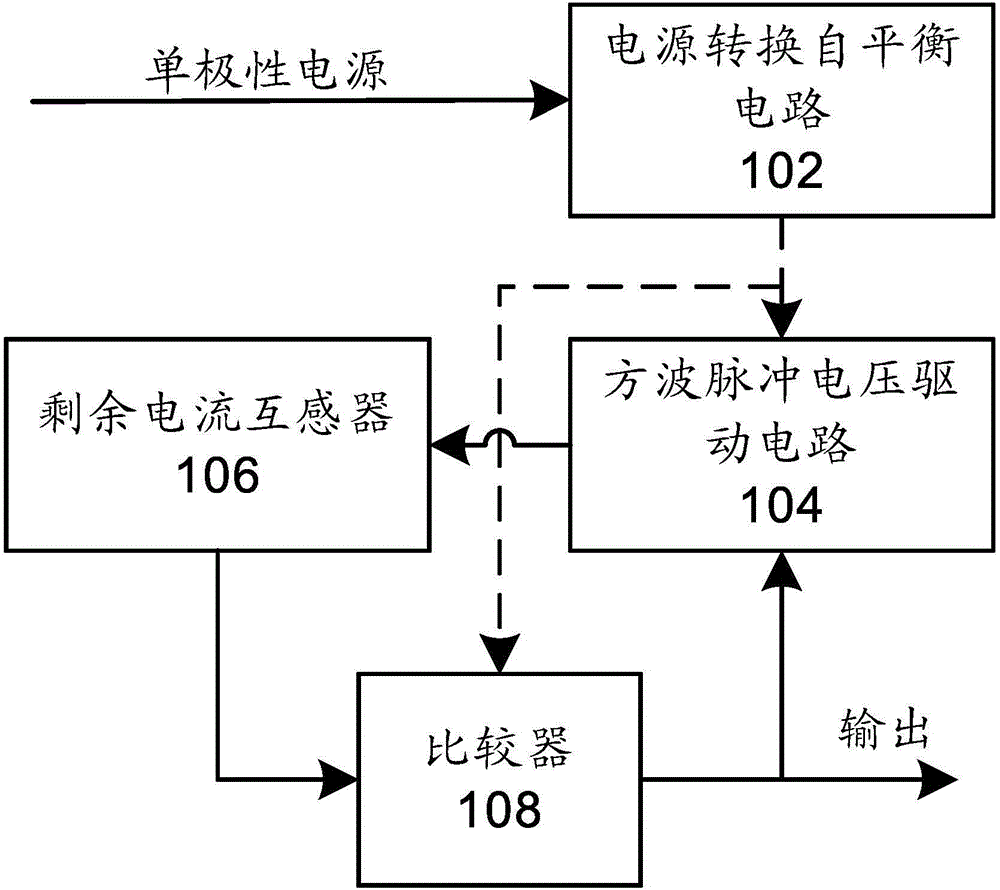
[0032] refer to figure 1 as shown, figure 1 A schematic circuit structure diagram of a DC residual current detection device according to an embodiment of the present invention is disclosed. The DC residual current detection device is driven by a unipolar power supply and includes: a power conversion self-balancing circuit 102 , a square wave pulse voltage drive circuit 104 , a residual current transformer 106 and a comparator 108 .

[0033] The input terminal of the power conversion self-balancing circuit 102 is connected to the unipolar power supply, the power conversion self-balancing circuit 102 con...


PUM


Abstract

A direct-current residual-current detecting device, driven by a monopolar power supply, comprises: a power conversion self-balancing circuit (102), a residual-current transformer (106), and a comparator (108). An input end of the power conversion self-balancing circuit (102) is connected to the monopolar power supply, the power conversion self-balancing circuit (102) converts monopolar power into bipolar power and outputs the bipolar power, and the power conversion self-balancing circuit (102) supplies power to another component. The residual-current transformer (106) is provided with an RL multivibrator, a square wave pulse voltage drive circuit (104) circularly exerts positive and negative direction voltages to a secondary winding of the residual-current transformer (106), and the residual-current transformer (106) outputs a corresponding sampling voltage. The comparator (108) obtains the sampling voltage output by the residual-current transformer (106), compares the sampling voltage with a voltage threshold of the comparator, and generates a positive and negative alternately square wave signal, the square signal is fed back as output of the comparator (108) to the square wave pulse voltage drive circuit (104) as a drive signal, and output of the comparator (108) is further used as output of the direct-current residual-current detecting device to represent the polarity and size of a direct-current residual-current.

Description

technical field [0001] The invention relates to residual current detection technology, more specifically, to a DC residual current detection device powered by a unipolar power supply. Background technique [0002] Traditional residual current detection methods include the AC-type residual current detection method for detecting only power frequency sinusoidal residual current, the A-type residual current detection method for detecting power frequency sinusoidal and pulsating DC residual current, and the A-type residual current detection method for detecting smooth DC residual current. Current B-type residual current detection method. Among them, the AC type residual current detection method usually uses the alternating residual current existing in the primary winding of the residual current transformer to generate an alternating magnetic field, thereby inducing a corresponding alternating induction in the secondary winding of the residual current transformer. current, so as ...

Claims


Application Information

Patent Timeline
Patent Type & Authority Applications(China)
IPC IPC(8): G01R19/00
CPCG01R15/185G01R19/10G01R31/52H02H3/33
Inventor 徐磊陈永亮杨世江
Owner SEARI ELECTRIC TECH
Why Eureka
Try Eureka