Numerical control program cutter path optimization method

A technology of tool path and numerical control program, applied in the field of numerical control, can solve the problems of cut parts, parts overcut, overtravel, etc., and achieve the effect of preventing cuts

Inactive Publication Date: 2015-09-23
JIANGXI HONGDU AVIATION IND GRP
View PDF5 Cites 2 Cited by
  • Summary
  • Abstract
  • Description
  • Claims
  • Application Information

AI Technical Summary

Problems solved by technology

[0011] The purpose of the present invention is to propose a method for optimizing the tool path of a numerical control program to solve the problem of overtravel caused by AC swing angle or BC swing angle machine tools due to excessive rotation angles.
Through the optimization of the motion trajectory after overtravel, the problem of overcutting of parts that may occur during the tool lifting and lowering processes during the machining process is solved, so as to realize the precision machining of aircraft structural parts
[0013] Optimize the path of the tool position trajectory at the overtravel, recalculate the movement trajectory of the machine tool after overtravel, and solve the problem of cutting parts

Method used


Image

  • Numerical control program cutter path optimization method
  • Numerical control program cutter path optimization method
  • Numerical control program cutter path optimization method

Examples


Embodiment 1

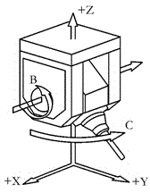
[0050] Combine below Figure 5 Give a detailed example. The tool goes from point A to point B to point C

[0051] Point A coordinates: X81.261 Y15.229 Z40.443 B2.541 C-184.756

[0052] Point B coordinates: X81.632 Y13.933 Z40.415 B2.381 C-188.851

[0053] Point C coordinates: X82.012 Y12.581 Z40.389 B2.226 C-193.713

[0054] The stroke of the C axis of the machine tool is: ±190°, and the coordinate of point C is: C-193.713, which has exceeded the stroke of the machine tool.

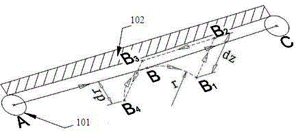
[0055] Assume that the cutting out and cutting in arc radius r=5, the tool retraction distance dr=3, the tool lifting height dz=50, the calculated B 1 ,B 2 ,B 3 ,B 4 The point coordinates are:

[0056] B 1 Point coordinates: X85.777 Y10.353 Z40.415 B2.381 C-188.851

[0057] B 2 Point coordinates: X83.890 Y10.813 Z90.377 B2.381 C-188.851

[0058] B 3 Point coordinates: X81.393 Y19.617 Z90.377 B2.381 C-188.851

[0059] B 4 Point coordinates: X83.280 Y19.156 Z40.415 B2.381 C-188.851

[0060] Th...


PUM


Abstract

The invention provides a numerical control program cutter path optimization method. A line segment ABC is a line taken from contour processing, a cutter moves from an A point to a C point via a B point, and the C point is the super-path point location. The method is characterized in that an arc path B-B1 is added at the B point along the tangent direction of an AB line segment, the cutter moves to a B1 point, the B1 point is far away from a part, and the cutter is withdrawn at the point; after the cutter is withdrawn at the B1 point, the cutter continues to move to a B2 point, the angle of the C axis is rotated, the cutter then moves to a B3 point, the cutter cuts at a B4 point, and the cutter-moving path employing arc cutting moves to the B point and finally to the C point. According to the method, the movement track after super-path is optimized, and the problem of part overcutting in the processes of cutter lifting and cutting is solved.

Description

technical field [0001] The invention belongs to the technical field of numerical control, and in particular relates to a method for optimizing a tool path of a numerical control program. Background technique [0002] In the mechanical processing industry, the manufacture of aircraft structural parts is different from general mechanical manufacturing parts, and has its own characteristics in structural shape and processing technology: [0003] 1) The parts have complex structures, different materials, high requirements for size and position accuracy, and often require multi-faceted processing; [0004] 2) The outline of the structural parts is related to the shape of the aircraft, and the machining accuracy and quality requirements are high, and most of them are ruled surfaces; [0005] 3) The equal-strength design of aircraft structural parts forms a large number of complex grooves; the groove walls adjacent to the contour are often ruled surfaces. [0006] According to th...

Claims


Application Information

Patent Timeline
Patent Type & Authority Applications(China)
IPC IPC(8): G05B19/19
CPCG05B19/19G05B2219/33128G05B2219/34093G05B2219/35097G05B2219/35099
Inventor 廖翔蒙志凌向兵飞
Owner JIANGXI HONGDU AVIATION IND GRP
Why Eureka
Try Eureka