
A real-time visible light remote sensing image cloud region detection method

A remote sensing image and detection method technology, applied in the direction of instruments, scene recognition, calculation, etc., can solve the problems of unsatisfactory real-time cloud area detection and high computational complexity

Inactive Publication Date: 2017-12-29
HUAZHONG UNIV OF SCI & TECH +1
View PDF2 Cites 0 Cited by
  • Summary
  • Abstract
  • Description
  • Claims
  • Application Information

AI Technical Summary

Problems solved by technology

However, the computational complexity of these texture features is high, which does not meet the requirements of real-time cloud region detection

Method used


Image

  • A real-time visible light remote sensing image cloud region detection method
  • A real-time visible light remote sensing image cloud region detection method
  • A real-time visible light remote sensing image cloud region detection method

Examples


Embodiment 1

[0053] Embodiment 1: Example of detection of cloud areas containing large cloud areas

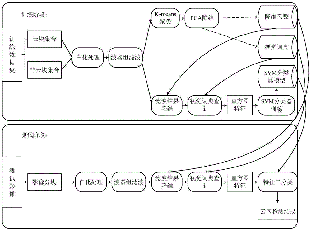
[0054] 1. Basic processing unit division

[0055] In order to control the processing granularity of the cloud area detection algorithm, the test image is first divided into non-overlapping G×G image sub-blocks. In this experiment, the test image is a panchromatic image, the pixel data bit depth is 8 bits, the spatial resolution is 2 meters, and the image block size G is set to 64.

[0056] 2. Whitening treatment

[0057] In order to maintain the invariance of feature extraction to illumination changes, the image sub-block is whitened, that is, all pixels in the image sub-block minus the mean value of the pixel value in the sub-block, divided by the standard deviation of the pixel value in the sub-block. The result of the whitening process is used as the input of the filter.

[0058] 3. Filtering based on unidirectional anisotropic Gaussian filter bank

[0059] Since the appearance of cl...

Embodiment 2

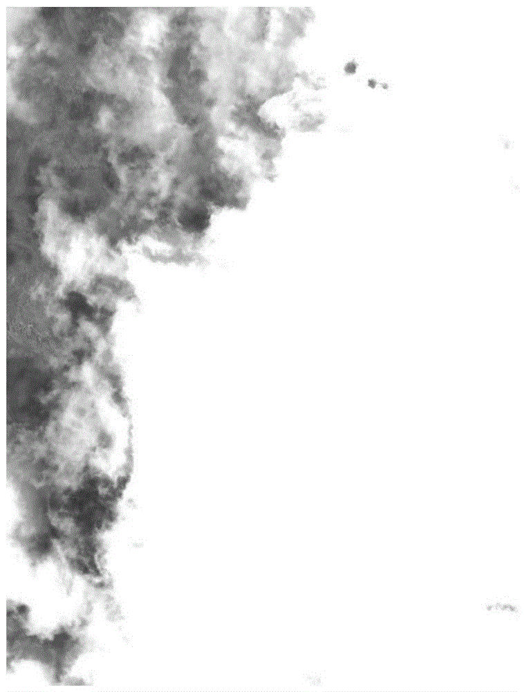
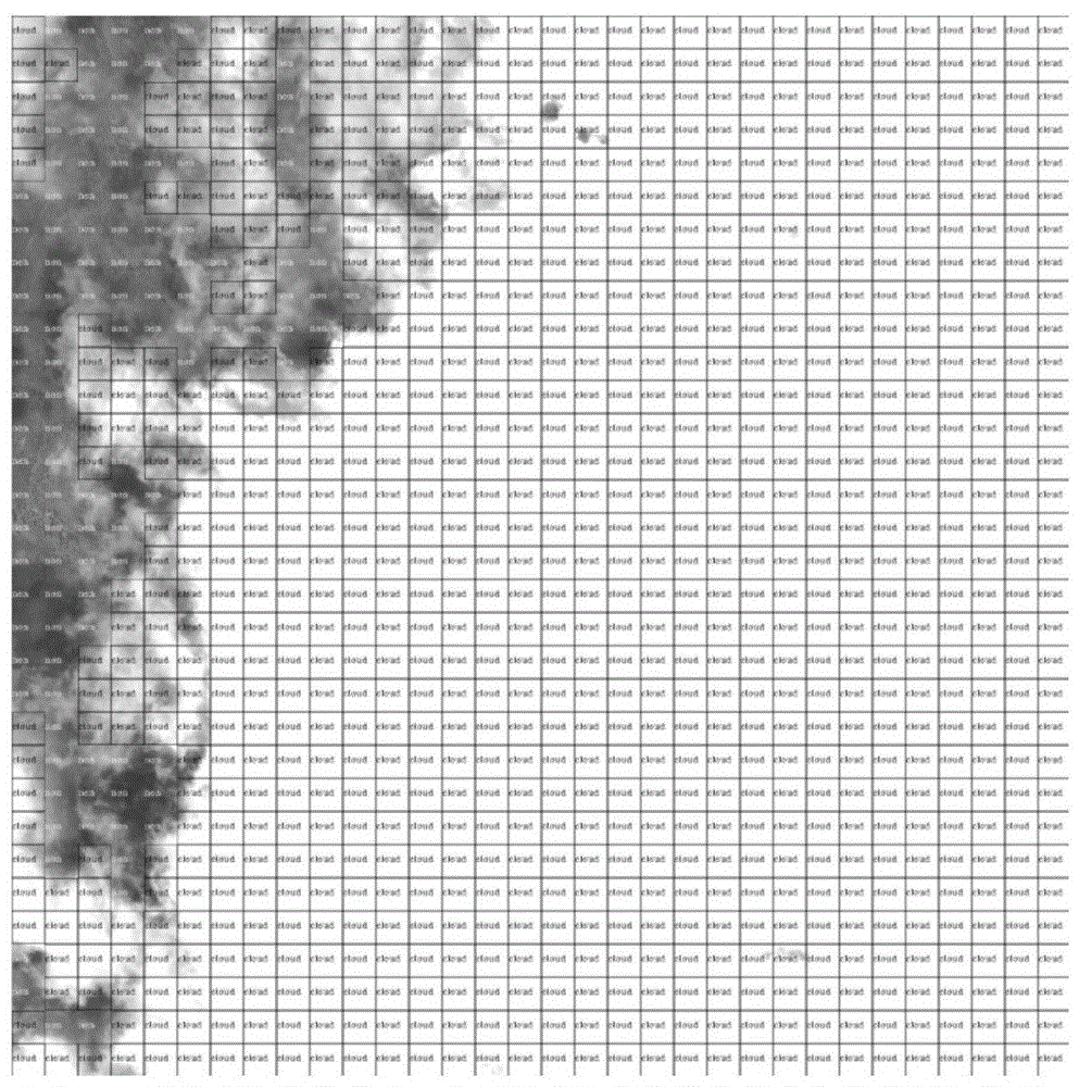
[0069] Embodiment 2: Example of detection of cloud areas containing small cloud areas

[0070] Its processing step is identical with embodiment 1. Figure 3(a) is the original remote sensing image containing a small cloud area, Figure 3(b) is the detection result of the cloud area based on the histogram feature of the visual word in six directions without dimensionality reduction, and Figure 3(c) is the detection result based on the single direction and The cloud area detection result of the visual word histogram feature without dimensionality reduction, Fig. 3 (d) is the cloud area detection result of the visual word histogram feature proposed by the present invention. By comparing Fig. 3(b), Fig. 3(c) and Fig. 3(d), the visual word histogram feature proposed by the present invention can achieve detection performance equivalent to that of the two variant feature extraction algorithms.


PUM


Abstract

A real-time visible light remote sensing image cloud area detection method, which belongs to image data processing methods; the invention includes the division of original image sub-blocks, then quickly extracting the features of each sub-block, and finally completing the cloud area detection through binary classification of the features of each sub-block. Aiming at the non-directional characteristics of the cloud area, the present invention proposes to use a single-direction anisotropic Gaussian filter bank to implement the filtering operation. In order to avoid the complexity of large-scale two-dimensional convolution operation, the single-direction anisotropic Gaussian filtering operation is realized through the infinite impulse response filter with row and column splitting. In order to reduce the complexity of visual word query in the process of visual word histogram feature generation, visual word first performs feature dimensionality reduction through principal component analysis, and then performs query. This dimensionality reduction query strategy can not only ensure query accuracy, but also greatly reduce query complexity. This method can meet the requirements of real-time cloud area detection on the satellite.

Description

technical field [0001] The invention belongs to image data processing methods, in particular to a real-time visible light remote sensing image cloud area detection method. Background technique [0002] Cloud area detection is one of the primary tasks and key technologies of visible light remote sensing image compression, transmission and processing. For a long time, visible light remote sensing images have been widely used due to their high resolution and high definition. However, an obvious weakness of visible light images is that cloud occlusion significantly reduces the observability of ground target information, and some thick cloud occlusion images are even unusable. Real-time thick cloud coverage area detection can play a positive role in improving the compression efficiency of remote sensing images, saving data transmission bandwidth and improving processing efficiency. From the data processing flow point of view, the cloud detection algorithm is at the forefront of...

Claims


Application Information

Patent Timeline
Patent Type & Authority Patents(China)
IPC IPC(8): G06K9/00G06K9/62
CPCG06V20/13G06V20/194G06F18/23213G06F18/2411
Inventor 李彦胜李情芸任菲菲刘磊伊成俊杜辉余毓杰谭毅华闫雪梅田金文
Owner HUAZHONG UNIV OF SCI & TECH
Learn More