Battery charging and discharging circuit

A charging and discharging circuit, charging and discharging technology, applied in the direction of battery circuit devices, circuit devices, collectors, etc., can solve the problems of low working efficiency of battery charging and discharging circuits, threats to the safety of battery operators, and reduce the efficiency of charging circuits. The effect of poor reliability, low work efficiency, and difficulty in heat dissipation

Inactive Publication Date: 2015-09-23
ANHUI DYNAMIC POWER
View PDF2 Cites 0 Cited by
  • Summary
  • Abstract
  • Description
  • Claims
  • Application Information

AI Technical Summary

Problems solved by technology

[0004] However, in the process of designing the battery charging and discharging circuit, the inventors found that there are at least the following problems in the prior art: the charging anti-reversal diode D1 in the existing battery charging and discharging circuit is arranged in the charging circuit, which obviously reduces the overall charging capacity. The efficiency of the loop, and prone to heating problems
In addition, there is no protection in the circuit for the dangerous consequences that may be caused by the failure of the charging switch SW1, discharging switch SW2 or other components, resulting in a low safety factor
Therefore, the existing battery charging and discharging circuit has low working efficiency and poor reliability, and poses a threat to the safety of the battery and operators during actual use.

Method used


Image

  • Battery charging and discharging circuit
  • Battery charging and discharging circuit
  • Battery charging and discharging circuit

Examples


Embodiment Construction

[0017] A battery charging and discharging circuit provided by an embodiment of the present invention will be described in detail below with reference to the accompanying drawings.

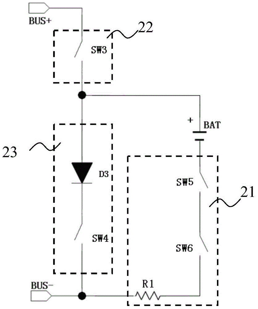
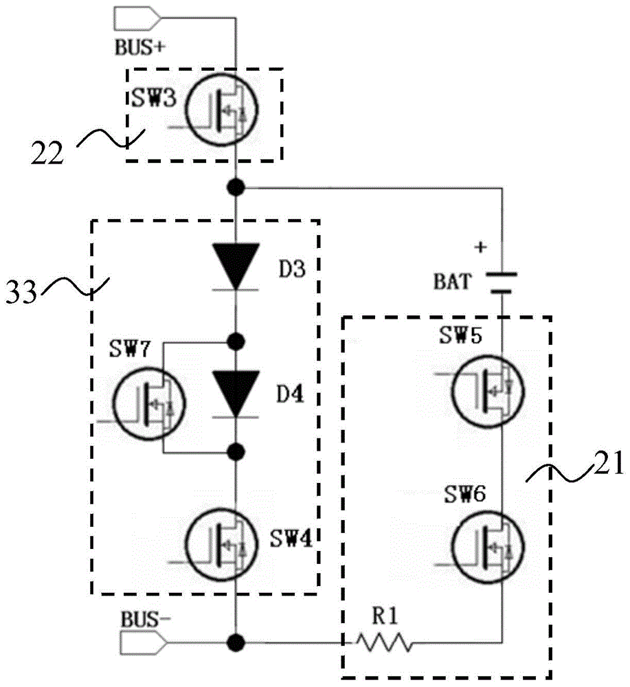
[0018] Such as figure 2 As shown, it is a battery charging and discharging circuit provided by the present invention; the battery charging and discharging circuit includes: power supply (BUS+, BUS-), charging and discharging branch 21, charging protection branch 22 and discharge protection branch 23;

[0019] The power supply (BUS+, BUS-) is used to charge the battery BAT through the charging protection branch 22;

[0020] The charging and discharging branch 21 is set at the negative terminal BAT- of the battery and the negative terminal BUS- of the power supply, and is used to control the charging or discharging operation of the battery, control the magnitude of the charging and discharging electric current and The current is sampled;

[0021] The charging protection branch 22 is arranged betwe...


PUM


Abstract

The invention provides a battery charging and discharging circuit. The battery charging and discharging circuit a power supply, a charging and discharging branch, a charging protection branch and a discharging protection branch. The power supply is used for supplying power to the charging and discharging circuit; the charging and discharging branch is arranged on a cathode end of a battery and a cathode end of the power supply and is used for controlling the charging and discharging operation performed on the battery, controlling the magnitudes of charging and discharging currents and carrying out sampling on the currents; the charging protection circuit is arranged between an anode end of the power supply and an anode end of the battery and is used for protecting normal charging operation of the battery charging circuit; and the discharging protection branch is arranged between the cathode end of the power supply and the anode end of the battery and is used for protection the normal discharging operation of the battery discharging circuit. By adopting the battery charging and discharging circuit provided by the invention, the working efficiency of the whole battery charging and discharging circuit is improved, and the heat dissipation problem is solved at the same time.

Description

technical field [0001] The invention relates to the technical field of power electronics, in particular to a battery charging and discharging circuit. Background technique [0002] With the development of power vehicles, high-power storage equipment and lithium battery technology, the demand for battery capacity is increasing, so the requirements for battery charging and discharging circuits are also getting higher and higher. Safety issues and efficiency issues have become a problem in battery charging and discharging circuits. key issues. [0003] Such as figure 1 Shown is a schematic circuit diagram of an existing battery charging and discharging circuit. Among them, BUS+ and BUS- are the power supply of the battery charging and discharging circuit, SW1 is the charging switch, SW2 is the discharging switch, D1 is the charging anti-reverse diode, and D2 is the discharging anti-reverse short circuit diode. BAT is the battery, and R1 is the sampling resistor. When the ba...

Claims


Application Information

Patent Timeline
Patent Type & Authority Applications(China)
IPC IPC(8): H02J7/00
Inventor 朱建华
Owner ANHUI DYNAMIC POWER
Why Eureka
Try Eureka