Eureka AIR delivers breakthrough ideas for toughest innovation challenges, trusted by R&D personnel around the world.

Current source type full-bridge PWM convertor with auxiliary converter circuit

A current source type, auxiliary transformer technology, applied in the field of electricity, can solve problems such as loss, and achieve the effect of improving work efficiency

Active Publication Date: 2015-09-23
XIDIAN UNIV +1
View PDF3 Cites 4 Cited by
  • Summary
  • Abstract
  • Description
  • Claims
  • Application Information

AI Technical Summary

Problems solved by technology

[0005] The present invention aims at the problems existing in the traditional current source type full-bridge PWM converter, and proposes a current source type full-bridge PWM converter with an auxiliary commutation circuit, which effectively solves the main problems in the traditional current source type full-bridge PWM converter. The problem of commutation and duty ratio loss of the lagging bridge arm exists to improve the working efficiency of the converter

Method used


Image

  • Current source type full-bridge PWM convertor with auxiliary converter circuit
  • Current source type full-bridge PWM convertor with auxiliary converter circuit
  • Current source type full-bridge PWM convertor with auxiliary converter circuit

Examples


Embodiment Construction

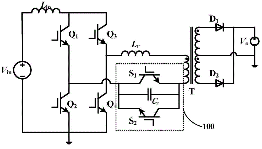
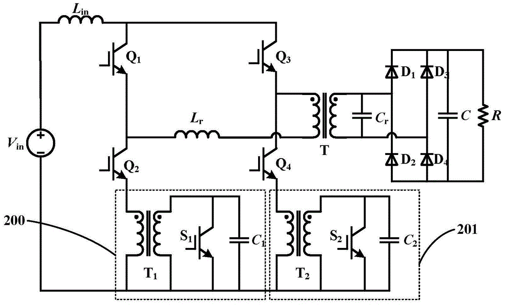
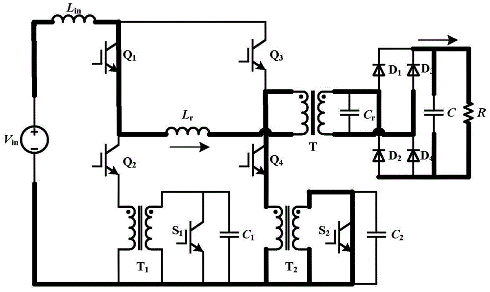
[0015] The embodiments of the present invention add auxiliary branches 200 and 201 to the lagging bridge arm respectively on the circuit topology of the traditional current source full-bridge PWM converter, thereby facilitating the completion of the commutation of the lagging bridge arm and reducing the original occupation The empty ratio is lost, thereby improving the working efficiency of the converter; at the same time, the circuit topology and working process are simple and easy to implement.

[0016] Such as figure 2 The current source full-bridge PWM converter circuit with auxiliary commutation circuit shown in the present invention includes an inverter circuit, a resonant network, an auxiliary branch, a transformer and a rectification and filtering network.

[0017] The inverter circuit adopts the power supply V in , input inductance L in and four main switches Q 1 , Q 2 , Q 3 , Q 4 The structure of the current source type full-bridge inverter circuit, the swit...


PUM


Abstract

The invention relates to a current source type full-bridge PWM convertor with auxiliary converter circuit. The current source type full-bridge PWM convertor comprises an inverter circuit, a resonance network, a transformer and a rectification filter network. Two auxiliary branch circuits are added in the current source type full-bridge PWM convertor. Each branch circuit is respectively composed of an auxiliary transformer, an auxiliary switch tube and a capacitor; the primary sides of the two auxiliary transformers are connected with emitters of two lagging bridge legs in series; the secondary sides of the two auxiliary transformers are connected with the switch tubes and capacitors in parallel; the current source type full-bridge PWM convertor is used for controlling cutoff and break-over of the two auxiliary switch tubes and coordinating the conversion current among four main switch tubes. By respectively adding two auxiliary branch circuits on the lagging bridge legs of a traditional current source type full-bridge PWM convertor and coordinating suitable drive pulse, the current source type full-bridge PWM convertor of the invention could effectively solve the two main problems, which are conversion current of the lagging bridge legs, and loss of duty ratio, existed in the current source type full-bridge PWM convertor, so as to improve work efficiency of the convertor.

Description

technical field [0001] The invention relates to the field of electricity, in particular to a technology for reducing switching loss of power devices, in particular to a current source type full-bridge PWM converter with an auxiliary commutation circuit. Background technique [0002] Full-bridge PWM (Pulse Width Modulation) converters have been widely used in high-power DC-DC (direct-current-direct current) power conversion. However, its lifespan and efficiency are two aspects that we need to focus on. The voltage source phase-shifted full-bridge converter operating in the ZVS (Zero Voltage Switching) state is one of the most widely used circuit topologies today. Its advantages lie in its simple structure and good working performance. However, in its circuit topology In the DC side, a large-capacity electrolytic capacitor is connected in parallel, so that the DC side voltage is basically pulsating, and the capacitor also plays a role in buffering reactive energy. However...

Claims


Application Information

Patent Timeline
Patent Type & Authority Applications(China)
IPC IPC(8): H02M3/335
Inventor 郑峰罗紫元励书杰龙民敬
Owner XIDIAN UNIV
Why Eureka
Eureka Blog
Learn More