
Improved deviation coupling control method suitable for multi-motor system

A technology of deviation coupling and control method, applied in the direction of multiple motor speed adjustment, etc., can solve the problems of large synchronization error, inability to synchronize performance and tracking performance to adjust and distinguish respectively

Active Publication Date: 2015-09-23
TIANJIN UNIV
View PDF2 Cites 26 Cited by
  • Summary
  • Abstract
  • Description
  • Claims
  • Application Information

AI Technical Summary

Problems solved by technology

In the master-slave control structure, the speed of the i+1 motor follows the speed of the i motor, that is, the speed of the i motor is more important than the speed of the i+1 motor, which to a certain extent reflects the The importance of speed in the system, but it has not been quantified, and the multi-motor speed synchronous control system using the master-slave control structure will produce relatively large synchronization errors under load disturbance; the traditional deviation coupling control structure in each single The speed compensator is added to the speed control channel of the motor to improve the synchronization performance of the system, so that the multi-motor speed synchronous control system can obtain better speed synchronization performance under the load disturbance than the application of the master-slave control structure, but it is essentially not Differentiate the importance of the speed of each motor in the system
In addition, due to the characteristics of the two control structures, the application of these two control structures can only comprehensively adjust the synchronization performance and tracking performance of the multi-motor speed synchronization control system, and select a relatively optimal value, which cannot be used for multi-motor speed synchronization. The synchronization performance and tracking performance of the control system can be adjusted separately (that is, decoupling adjustment)

Method used


Image

  • Improved deviation coupling control method suitable for multi-motor system
  • Improved deviation coupling control method suitable for multi-motor system
  • Improved deviation coupling control method suitable for multi-motor system

Examples


Embodiment Construction

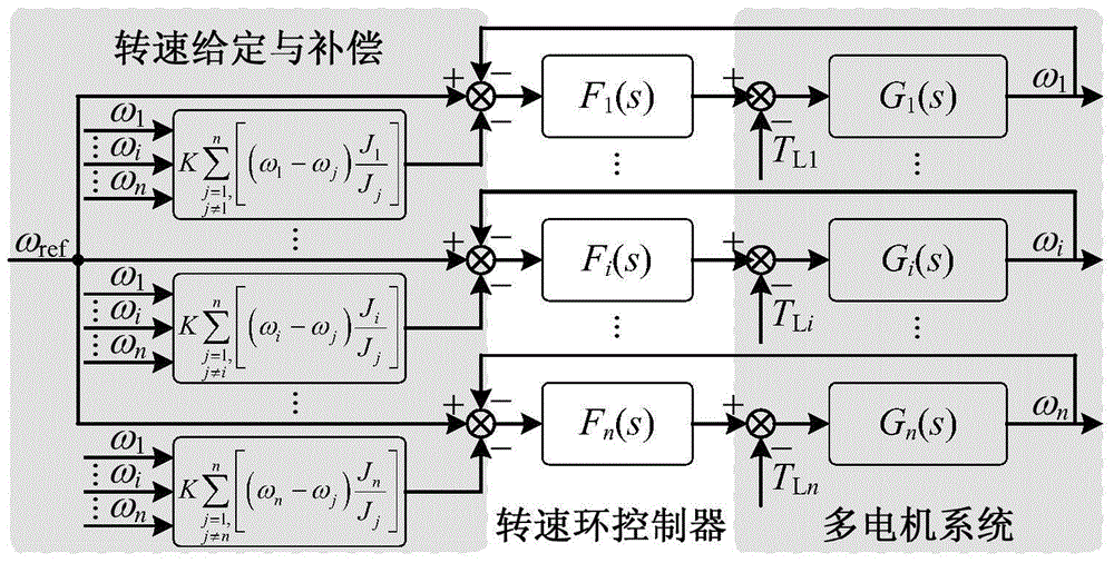
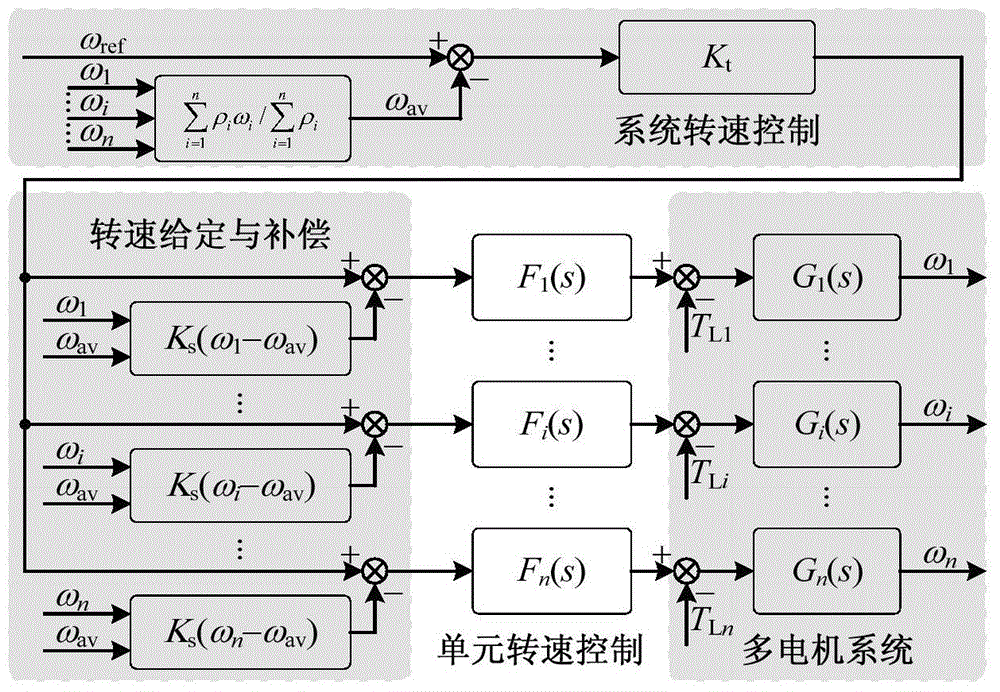
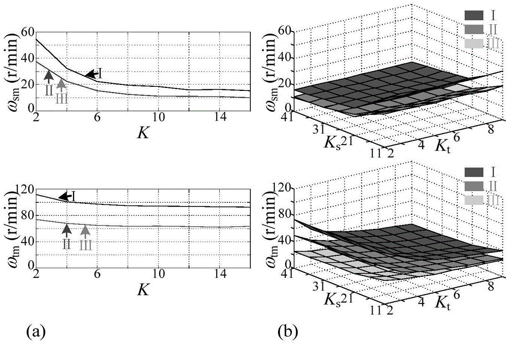
[0032]The purpose of the present invention is to solve the problems existing in the traditional deviation coupling control structure that the importance of each motor speed in the system is not considered and the synchronous performance and tracking performance of the system cannot be decoupled and adjusted, and an improved deviation coupling control structure is proposed. The structure reflects the importance of the speed of each motor in the system through the speed weight coefficient, and can decouple the synchronization performance and tracking performance of the system by adjusting the synchronization coefficient and tracking coefficient in the structure. At the same time, the structure can effectively improve the synchronization performance and tracking performance of the system under the premise of applying a proportional-integral control strategy (PI control strategy), that is, without greatly increasing the calculation amount of the processor.

[0033] In order to achi...


PUM


Abstract

The invention relates to the field of multi-motor cooperative control, and aims at providing an improved deviation coupling control structure suitable for a multi-motor system so that synchronization performance and tracking performance of the system can be effectively enhanced. Therefore, the adopted technical scheme is an improved deviation coupling control method suitable for the multi-motor system. Rotating speed weight coefficient reflecting degree of importance of motor rotating speed is utilized, and multi-motor rotating speed synchronization control is divided into two phases of system rotating speed control and unit rotating speed control for controlling. The concrete structure comprises six parts: (1) calculation of a system rotating speed value; (2) control of system rotating speed; (3) calculation of unit synchronization error; (4) calculation of unit error; (5) control of unit rotating speed; (6) and multi-motor rotating speed synchronization control. The improved deviation coupling control method suitable for the multi-motor system is mainly applied to multi-motor cooperative control.

Description

technical field [0001] The invention relates to the field of multi-motor coordinated control, in particular to the field of multi-motor speed coordinated control. Specifically, it relates to an improved deviation coupling control method suitable for multi-motor systems. Background technique [0002] In recent years, with economic transformation and industrial upgrading, industrial production such as rail transit, papermaking, printing, and metallurgy urgently needs multi-motor high-performance cooperative control technology, and multi-motor cooperative control technology has also become a research hotspot in the scientific research community. [0003] In industrial production, for a multi-motor speed synchronous control system, the importance of each motor speed in the system is generally different. For example, in some printing press systems, the speed of the speed reference motor is the most important, the speed of the unwinding motor is second, and the speed of the windi...

Claims


Application Information

Patent Timeline
IPC IPC(8): H02P5/50
Inventor 史婷娜刘昊夏长亮耿强
Owner TIANJIN UNIV
Learn More