An impinging flow hypergravity liquid-liquid extractor
An extractor and gravity technology, which is applied in the field of impinging flow supergravity liquid-liquid extractor, can solve the problems of less development of supergravity equipment, achieve the effect of prolonging residence time, prolonging reaction time and increasing adjustable parameters
- Summary
- Abstract
- Description
- Claims
- Application Information
AI Technical Summary
Problems solved by technology
Method used
Image
Examples
Embodiment 1
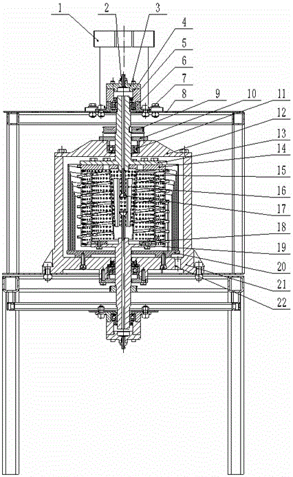
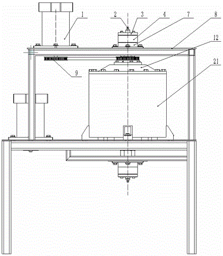
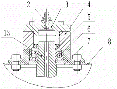
[0033] Such as Figures 1 to 11As shown, the impinging flow supergravity liquid-liquid extractor includes a power transmission structure, a liquid collector mechanism, a rotating shaft structure, a liquid mass transfer structure and a fixed component structure. The power transmission structure is two sets of symmetrical power transmission mechanisms. The liquid collection The mechanism includes faucet 2, liquid collector end cover 3, liquid collector 4 and lip seal ring 5, the liquid collector mechanism is two sets of upper and lower symmetrical structures, the rotating shaft structure includes bearing 6, bearing seat 7 and rotating shaft, the rotating shaft The structure is two sets of upper and lower symmetrical structures. The rotating shaft is divided into upper and lower symmetrical upper rotating shaft 13 and lower rotating shaft 19 according to the position. The liquid mass transfer structure includes the upper rotating shaft spiral porous plate 14, cone porous plate 15,...
Embodiment 2
[0040] Such as Figures 1 to 11 As shown, the impinging flow supergravity liquid-liquid extractor includes a power transmission structure, a liquid collector mechanism, a rotating shaft structure, a liquid mass transfer structure and a fixed component structure. The power transmission structure is two sets of symmetrical power transmission mechanisms. The liquid collection The mechanism includes faucet 2, liquid collector end cover 3, liquid collector 4 and lip seal ring 5, the liquid collector mechanism is two sets of upper and lower symmetrical structures, the rotating shaft structure includes bearing 6, bearing seat 7 and rotating shaft, the rotating shaft The structure is two sets of upper and lower symmetrical structures. The rotating shaft is divided into upper and lower symmetrical upper rotating shaft 13 and lower rotating shaft 19 according to the position. The liquid mass transfer structure includes the upper rotating shaft spiral porous plate 14, cone porous plate 15...
Embodiment 3
[0047] Such as Figures 1 to 11 As shown, the impinging flow supergravity liquid-liquid extractor includes a power transmission structure, a liquid collector mechanism, a rotating shaft structure, a liquid mass transfer structure and a fixed component structure. The power transmission structure is two sets of symmetrical power transmission mechanisms. The liquid collection The mechanism includes faucet 2, liquid collector end cover 3, liquid collector 4 and lip seal ring 5, the liquid collector mechanism is two sets of upper and lower symmetrical structures, the rotating shaft structure includes bearing 6, bearing seat 7 and rotating shaft, the rotating shaft The structure is two sets of upper and lower symmetrical structures. The rotating shaft is divided into upper and lower symmetrical upper rotating shaft 13 and lower rotating shaft 19 according to the position. The liquid mass transfer structure includes the upper rotating shaft spiral porous plate 14, cone porous plate 15...
PUM
 Abstract
Description
Claims
Application Information
 - R&D
- Intellectual Property
- Life Sciences
- Materials
- Tech Scout
- Unparalleled Data Quality
- Higher Quality Content
- 60% Fewer Hallucinations
Browse by: Latest US Patents, China's latest patents, Technical Efficacy Thesaurus, Application Domain, Technology Topic, Popular Technical Reports.
© 2025 PatSnap. All rights reserved.Legal|Privacy policy|Modern Slavery Act Transparency Statement|Sitemap|About US| Contact US: help@patsnap.com


