Reverse osmosis membrane element

A technology for reverse osmosis membranes and elements, applied in the field of reverse osmosis membrane elements, can solve the problems of low water production efficiency, small water production volume, and low recovery rate of pure water machines of reverse osmosis membrane elements.

Active Publication Date: 2015-09-30
GREE ELECTRIC APPLIANCES INC
View PDF5 Cites 18 Cited by
  • Summary
  • Abstract
  • Description
  • Claims
  • Application Information

AI Technical Summary

Problems solved by technology

The reverse osmosis membrane element with this structure has few supporting point structures, the element has poor pressure resistance, and the water inlet and pure water flow channels are

Method used


Image

  • Reverse osmosis membrane element
  • Reverse osmosis membrane element
  • Reverse osmosis membrane element

Examples


Embodiment 1

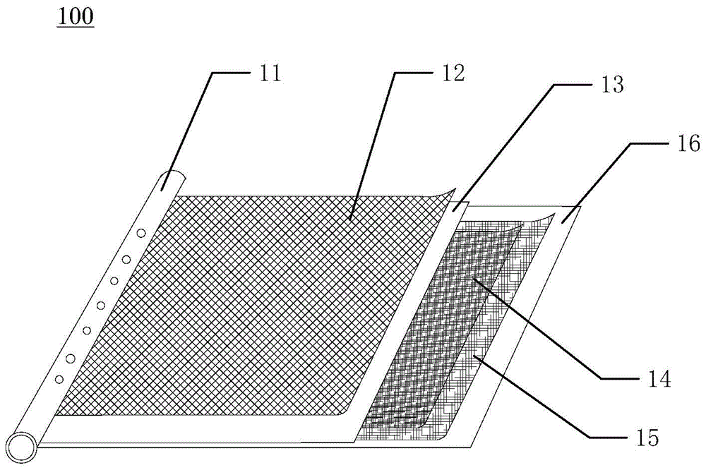
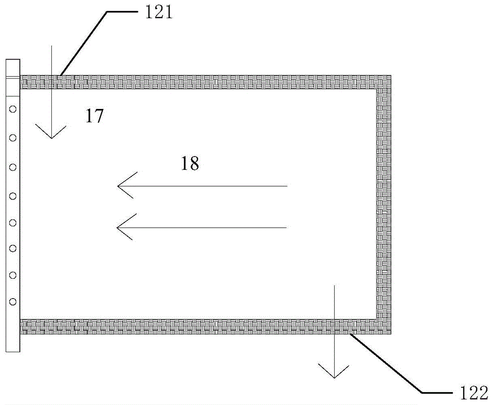
[0023] Such as figure 1 , 2 As shown, the reverse osmosis membrane element 100 in this embodiment includes a central pipe 11, a water inlet spacer 12, a first reverse osmosis membrane 13, a first pure water diversion cloth 14, a second pure water diversion cloth 15 and a first pure water diversion cloth 15. Two reverse osmosis membranes 16, the water inlet spacer 12, the first reverse osmosis membrane 13, the first pure water diversion cloth 14, the second pure water diversion cloth 15 and the second reverse osmosis membrane 16 are stacked successively, they One side of the central tube is fixed on the outer wall of the central tube 11, and finally wound on the central tube 11. The first pure water guide cloth 14 and the second pure water guide cloth 15 form a multi-support point structure. A product water channel 18 is formed between the two opposite surfaces of the first reverse osmosis membrane 13 and the second reverse osmosis membrane 16 , and an inflow channel 17 is fo...

Embodiment 2

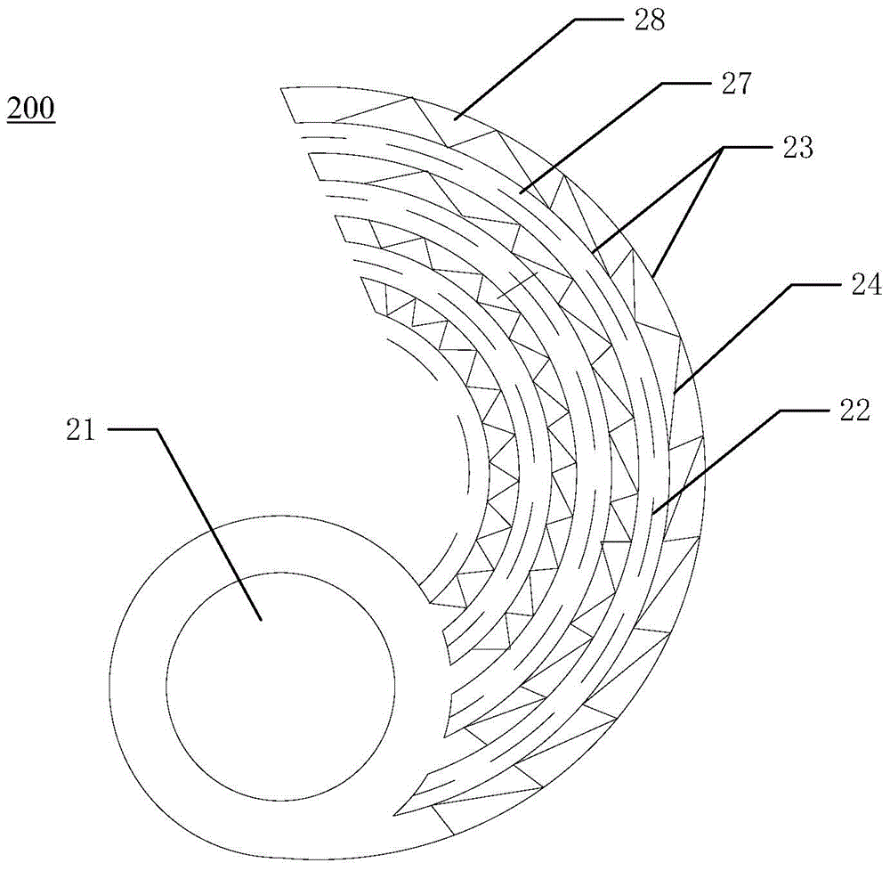
[0027] The reverse osmosis membrane element 200 in this embodiment is as image 3 As shown, it includes a central pipe 21 , a water inlet spacer 22 , a reverse osmosis membrane 23 and a pure water diversion cloth 24 . The water inlet screen 22, the reverse osmosis membrane 23 and the pure water diversion cloth 24 all have multiple layers, and the water inlet flow channel 27 and the water production flow channel 28 are respectively formed between the adjacent two layers of reverse osmosis membranes 23. The water flow channel 27 and the water production flow channel 28 are arranged at intervals, that is, except for the innermost and outermost two layers, a water production flow channel 28 is arranged on both sides of a water inlet flow channel 27, and a water production flow channel 28 is arranged on both sides of a water production flow channel 28. Water channel 27. A layer of the water inlet spacer 22 is placed in one water inlet flow channel 27, and a layer of pure water div...

Embodiment 3

[0029] The reverse osmosis membrane element 300 in this embodiment is as Figure 4 As shown, it includes a central pipe 31 , a water inlet spacer 32 , a reverse osmosis membrane 33 and a pure water diversion cloth 34 . The structure of the reverse osmosis membrane element 300 in this embodiment is substantially the same as that of the reverse osmosis membrane element 200 in Embodiment 2, the difference is that in this embodiment, the inlet water separator 32 is bent into a wave shape or a fan shape , the bent water inlet spacer 32 forms a multi-support point structure. Preferably, the layer spacing between adjacent layers of the wave shape (see Figure 5 L) shown in is 15-24 mm, the bending angle of the sector is 60-120 degrees, and the thickness of the pure water guide cloth 24 after bending is 0.3-0.5 mm. In this embodiment, the water inlet spacer 32 is bent into a wave shape or a fan shape, which increases the filtration area of ​​the water inlet flow channel, thereby inc...


PUM

PropertyMeasurementUnit
Bend angleaaaaaaaaaa
Thicknessaaaaaaaaaa
Bend angleaaaaaaaaaa

Abstract

The invention relates to a reverse osmosis membrane element which comprises a central pipe, a plurality of water inlet partition nets, a plurality of reverse osmosis membranes and multiple pieces of pure water diversion cloth. The water inlet partition nets, the reverse osmosis membranes and the multiple pieces of pure water diversion cloth are wound around the central pipe. The multiple pieces of pure water diversion cloth are communicated with an inner cavity of the central pipe. A water inlet channel and a water producing channel are formed between every two adjacent reverse osmosis membranes and are arranged in a spaced mode. The water inlet partition nets are located in the water inlet channels. The multiple pieces of pure water diversion cloth are located in the water producing channels. The water inlet partition nets and/or the multiple pieces of pure water diversion cloth are each of a multi-supporting-point structure. The water inlet partition nets and/or the multiple pieces of pure water diversion cloth are each of the multi-supporting-point structure, and therefore load bearing contact points of the reverse osmosis membrane element can be effectively increased, the stress tolerance of the reverse osmosis membrane element is improved, the area of the water inlet channels or the water producing channels is enlarged, and the water producing flow of the reverse osmosis membrane element can be effectively improved.

Description

technical field [0001] The invention relates to the technical field of filtration, in particular to a reverse osmosis membrane element. Background technique [0002] The reverse osmosis membrane element is the core component of the pure water machine, and the water production effect of the pure water machine is directly related to the water production efficiency of the reverse osmosis membrane element. The structure of reverse osmosis membrane elements currently on the market is to place a layer of pure water guide cloth between two reverse osmosis membranes, then roll it on the central tube, and install it inside the filter for use. The reverse osmosis membrane element with this structure has few support points, poor pressure resistance of the element, less water inlet and pure water flow channels, small water production, easy pollution of the reverse osmosis membrane, and low water production efficiency of the reverse osmosis membrane element. The recovery rate is low. ...

Claims


Application Information

Patent Timeline
IPC IPC(8): B01D61/08C02F1/44
Inventor 李一然秦利利杨勇吕剑明张量
Owner GREE ELECTRIC APPLIANCES INC
Why Eureka
Try Eureka