Bending device based on rolling bending and torque control

A bending device and rolling technology, applied in the field of sheet metal processing, can solve problems such as long processing cycle, potential safety hazards, sheet adjustment, etc., achieve the effects of reducing cracks and burrs, improving work reliability, and convenient height and angle

Inactive Publication Date: 2015-09-30
SUZHOU BIANTONG SENSING TECH
View PDF6 Cites 1 Cited by
  • Summary
  • Abstract
  • Description
  • Claims
  • Application Information

AI Technical Summary

Problems solved by technology

[0003] At present, there are some small bending machines on the market. When working, the bending torque is set by the experience of the workers. It cannot be adjusted in real time according to the thickness of the sheet. The processing quality of the sheet is not high. When the bending torque is not suitable, there are cracks in the sheet after bending. Defects; lack of angle control device, prone to excessive bending, and potential safety hazards; after bending, the concave plate material needs further processing due to cracks and burrs due to extrusion, resulting in a long processing cycle; according to experience, clamping is Processed parts have the defects of excessive deformation caused by excessive clamping force and looseness caused by too small clamping force; lack of sheet positioning structure, defects of bending offset and empty bending

Method used


Image

  • Bending device based on rolling bending and torque control
  • Bending device based on rolling bending and torque control
  • Bending device based on rolling bending and torque control

Examples


Embodiment Construction

[0015] The specific implementation manner of the present invention will be described below in conjunction with the accompanying drawings.

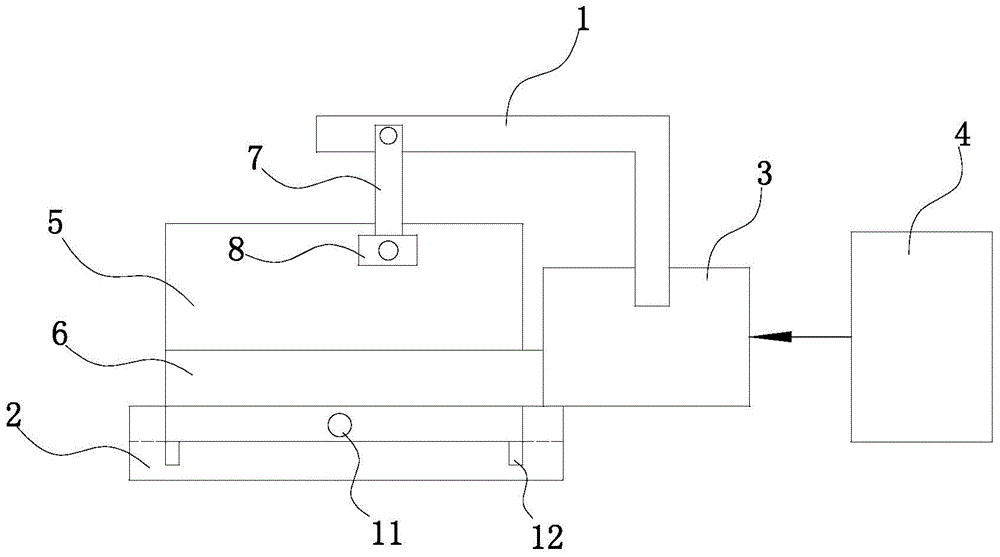
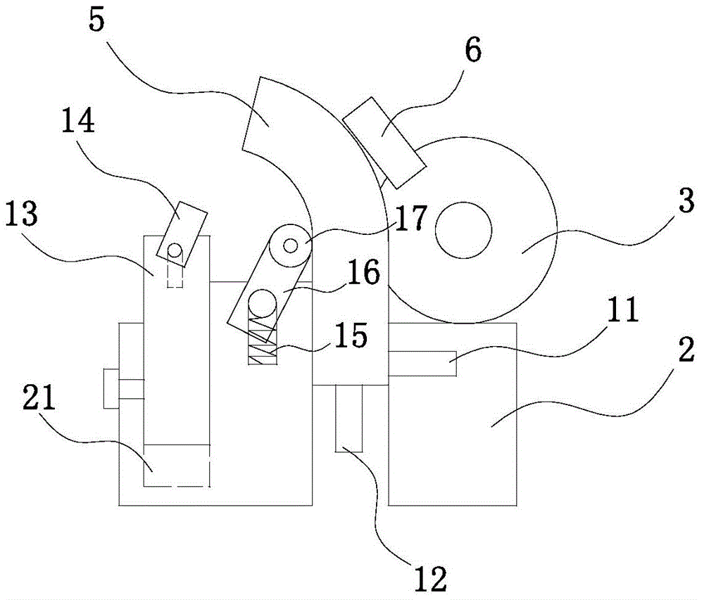
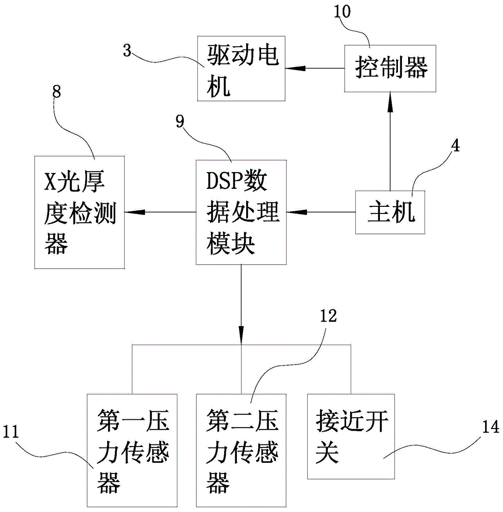
[0016] Such as figure 1 , figure 2 and image 3 As shown, the bending device based on rolling bending and torque regulation in this embodiment includes a drive motor 3 installed on the frame 1, a clamping and fixing seat 2 and a host 4 that controls the drive motor 3, and the drive motor 3 The bending shaft 6 is installed on the motor shaft, and the workpiece 5 is installed on the clamping seat 2;

[0017] It also includes an X-ray thickness detector 8 installed on the frame 1 by means of a bracket 7, a proximity switch 14 installed on the clamping seat 2, a first pressure sensor 11, a second pressure sensor 12 and a roller 17, and the proximity switch 14 is installed in the clamping groove 21 of the clamping seat 2 by means of the support rod 13, the first pressure sensor 11 and the second pressure sensor 12 are located on the side an...


PUM


Abstract

The invention relates to a bending device based on rolling bending and torque control. The device comprises a drive motor on a rack, a clamping and fixing base and a main machine. A bending shaft is installed on the drive motor, and a machined part is arranged on the clamping and fixing base. The device further comprises an X-ray thickness detector, a proximity switch, a first pressure sensor, a second pressure sensor and a rolling shaft, wherein the X-ray thickness detector is installed on the rack through a support, the proximity switch is installed on the clamping and fixing base, the first pressure sensor and the second pressure sensor are located on the side face and the bottom face of the machined part respectively, and the rolling shaft is arranged on the concave face side of the machined part. Clamping force is controlled through the pressure sensors, and excessive deformation and loosening of plates are avoided. Bending at the most proper torque is carried out, and machining quality is improved. The proximity switch is arranged to automatically control the bending angle, and excessive bending is prevented. The inner concave face of the machined part is rolled through the rolling shaft, and cracks and burrs on the concave face are reduced.

Description

technical field [0001] The invention relates to the technical field of sheet metal processing, in particular to a sheet metal bending device. Background technique [0002] Currently used sheet metal bending machine, commonly used two types of organic pillow hydraulic, mechanical bending machine is to use the motor through a series of gear transmission and eccentric wheel to realize the up and down movement of the working joint. The hydraulic bending machine is realized by using a hydraulic cylinder and a complete set of oil circuit control components. These bending machines play an important role in the mass production of large enterprises, but due to their high price and complex structure, their popularization is limited. With the development of the commodity economy, there are more and more stamping parts for small commodities for daily use. Small enterprises and even self-employed households urgently need sheet metal bending machines with low price and simple structure. ...

Claims


Application Information

Patent Timeline
Patent Type & Authority Applications(China)
IPC IPC(8): B21D5/00B21C51/00
CPCB21D5/004B21C51/00B21D5/04
Inventor 不公告发明人
Owner SUZHOU BIANTONG SENSING TECH
Why Eureka
Try Eureka