Compound machine pneumatic loading device

A compound machine and frame technology, applied in the field of mechanical equipment, can solve problems such as increased medical expenses, work-related compensation expenses, transportation expenses and related management costs, increased company labor costs and overtime expenses, and operator waist sprains, etc., to achieve reduction Work-related injury medical expenses and work-related expenses, avoidance of lumbar muscle injuries and work-related accidents, effects of reducing lumbar muscle injuries and work-related accidents

Inactive Publication Date: 2015-09-30
SHANGHAI JINZHIDA COMPOSITE MATERIAL
View PDF4 Cites 0 Cited by
  • Summary
  • Abstract
  • Description
  • Claims
  • Application Information

AI Technical Summary

Problems solved by technology

[0002] Composite PVC materials used in automotive interiors generally have a weight of 150-200KG per roll during composite processing and production. Each time, 4 production workers need to work together to manually lift, load and unload materials, and the material is fed on the composite machine. The height needs to be 80cm. Repeatedly moving more than 200 times a day often causes the operator's waist to be sprained and lumbar muscle strained, and the hands and feet will also be injured. Work-related injuries often occur; at the same time, the company will increase a lot of medical expenses, work-related compensation costs, Transportation costs and related management costs; and because of low labor efficiency, low product output rate, and a large number of workers, the company's labor costs and overtime costs are increased; workers are also highly mobile because they cannot adapt to heavy physical labor
In response to this problem, after in-depth research, development and multiple tests, our R&D personnel finally developed an inventive pneumatic feeding device that can solve the above problems. Although the appearance of the device is small, the effect is very significant

Method used


Image

  • Compound machine pneumatic loading device
  • Compound machine pneumatic loading device

Examples


Embodiment Construction

[0011] The following will clearly and completely describe the technical solutions in the embodiments of the present invention with reference to the accompanying drawings in the embodiments of the present invention. Obviously, the described embodiments are only some, not all, embodiments of the present invention. Based on the embodiments of the present invention, all other embodiments obtained by persons of ordinary skill in the art without making creative efforts belong to the protection scope of the present invention.

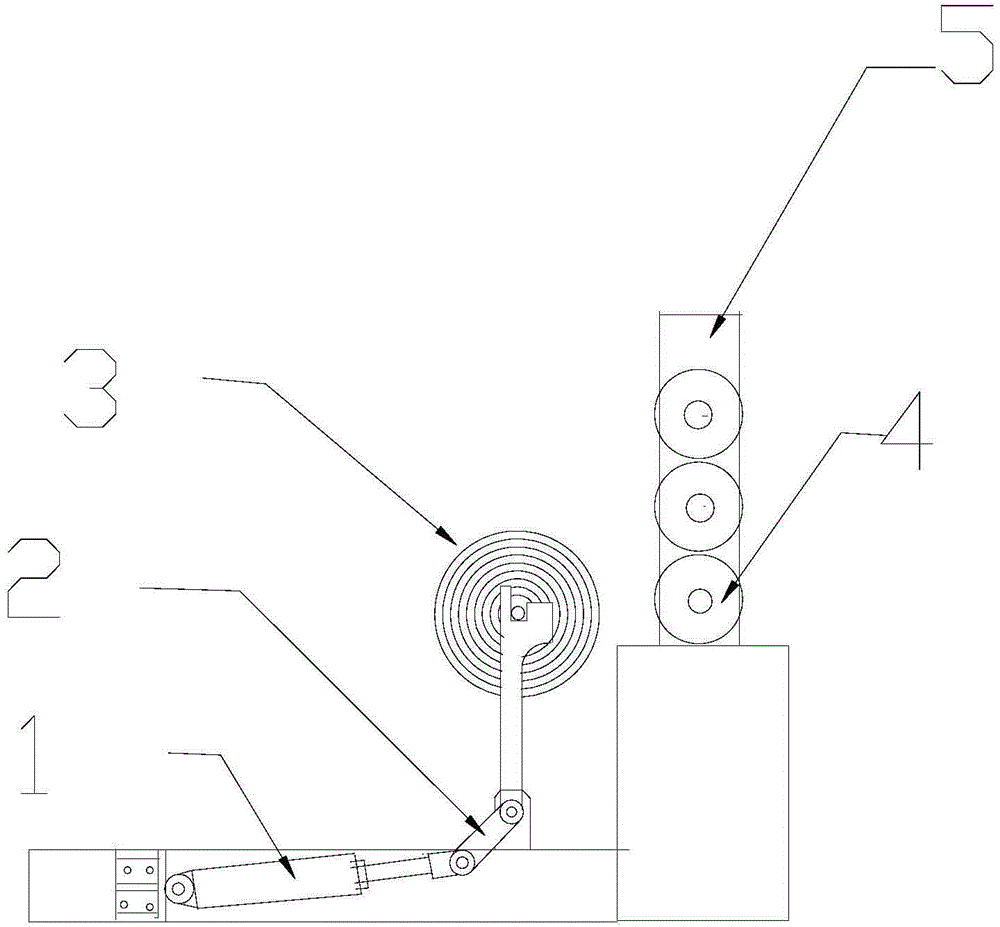
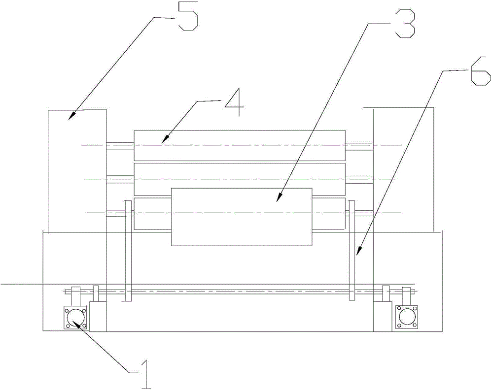
[0012] Such as figure 1 , figure 2 As shown, a pneumatic feeding device for a composite machine includes a motor 1, a column 6, and a transmission arm 2 on the motor. The transmission arm 2 is connected to the bottom of the column 6, and the joint is connected by rolling. A groove is provided, and the height of the left protrusion forming the groove is twice as high as that of the right protrusion forming the groove.

[0013] A pneumatic feeding device for ...


PUM


Abstract

The invention discloses a compound machine pneumatic loading device, which has a breakthrough improvement on the defects of the prior art. Compared with the problems existing in the technical background, the invention has the beneficial effects that due to the adoption of an automation pneumatic loading and unloading device, the labor intensity of workers is greatly relieved; the number of the workers is reduced; and the labor cost is reduced. Meanwhile, since automation replaces manual work, the lumbar muscular injury and the industrial accident of the workers are reduced and avoided; the industrial injury treatment expense and the industrial injury correlative expense which are burdened by a company are also reduced; finally the technological content of production mechanization of the company is increased; and the labor production efficiency is improved.

Description

technical field [0001] The invention relates to a mechanical device, in particular to a pneumatic feeding device for a composite machine. Background technique [0002] Composite PVC materials used in automotive interiors generally have a weight of 150-200KG per roll during composite processing and production. Each time, 4 production workers need to work together to manually lift, load and unload materials, and the material is fed on the composite machine. The height needs to be 80cm. Repeatedly moving more than 200 times a day often causes the operator's waist to be sprained and lumbar muscle strained, and the hands and feet will also be injured. Work-related injuries often occur; at the same time, the company will increase a lot of medical expenses, work-related compensation costs, Transportation costs and related management costs; and because of low labor efficiency, low product output rate, and a large number of workers, the company's labor costs and overtime costs have i...

Claims


Application Information

Patent Timeline
Patent Type & Authority Applications(China)
IPC IPC(8): B29C31/08
Inventor 江小舟
Owner SHANGHAI JINZHIDA COMPOSITE MATERIAL
Why Eureka
Try Eureka