Injector Corrosion Isolation Seals

A technology for injectors and sealing components, which is applied to fuel injection devices, engine sealing, special fuel injection devices, etc., and can solve problems such as injectors not working.

Active Publication Date: 2017-09-15
VITESCO TECH USA
View PDF4 Cites 0 Cited by
  • Summary
  • Abstract
  • Description
  • Claims
  • Application Information

AI Technical Summary

Problems solved by technology

Subsequent corrosion and electrical shorts may render the injector inoperable

Method used


Image

  • Injector Corrosion Isolation Seals
  • Injector Corrosion Isolation Seals
  • Injector Corrosion Isolation Seals

Examples


Embodiment Construction

[0013] The following description of the preferred embodiments is merely illustrative in nature and in no way intended to limit the invention, its application or uses.

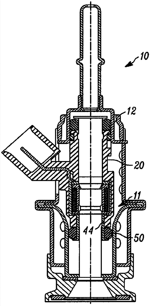
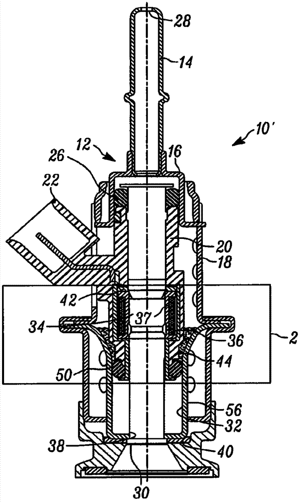
[0014] refer to figure 2 , a fluid injector according to an embodiment of the present invention is shown generally at 10'. The injector 10 ′ includes an inlet cap structure, shown generally at 12 , having a cap tube 14 and an inlet cap 16 . When the injector is configured as an RDU of a vehicle's selective catalytic reduction (SCR) system, the cap pipe 14 can be connected to a source of reductant. The inlet cap 16 is connected to a shroud 18 and the shroud 18 substantially surrounds a portion of the plastic body 20 with the connector 22 .

[0015] A portion of the inlet pipe 24 is disposed within the main body 20 . A primary sealing member 26 , such as an elastomeric O-ring, surrounds a portion of the inlet tube 24 to provide a seal between the inlet tube 24 , the inlet cap 16 and the body 20 .

[0016] Fl...


PUM


Abstract

A fluid injector includes a valve assembly constructed and arranged to control the flow of fluid from an inlet to an outlet of the injector. A metal housing surrounds at least a portion of the valve assembly. A plastic body is molded over at least a portion of the housing. The distal end of the body defines an integral stepped portion extending from the body. The stent surrounds at least the distal end of the body. The sealing member contacts at least surfaces of the stepped portion and the bracket to prevent liquid from entering a space between the case and the body.

Description

[0001] This application claims priority to US Provisional Patent Application No. 61 / 900,718, filed November 6, 2013, the disclosure of which is hereby incorporated by reference into this specification. technical field [0002] The present invention relates generally to seals for fluid injectors of reductant delivery units (RDUs), and more particularly to improved seals for preventing corrosion in injectors. Background technique [0003] refer to figure 1 A typical fluid injector 10 configured as an RDU employs a plastic body 20 molded over a metal housing 44 . These components are located in the area indicated by arrow 11 where liquids from the environment, such as rainwater and salt water, can collect. Salt water is known to be very corrosive and can short out electrical components due to its ionic properties. The different rates of thermal expansion of the molded plastic body 20 and the metal housing 44 create a gap that allows pooled liquid to be drawn through the O-rin...

Claims


Application Information

Patent Timeline
Patent Type & Authority Patents(China)
IPC IPC(8): F01N3/28
CPCF02M51/0664F02M61/08F02M2200/05F02M2200/9015F02M2200/16F01N3/2066F01N2610/1453Y02A50/20Y02T10/12F01N3/24F01N3/206F16J15/34
Inventor T·M·德特韦勒R·W·麦克法兰K·A·肖
Owner VITESCO TECH USA
Why Eureka
Try Eureka