Cooling method and device for engine core module

A cooling method and core cabin technology, applied in the cooling of the engine, the cooling system of the power plant, the engine components, etc., can solve the problems of difficult to meet the temperature requirements, extrinsic aerodynamic losses, and large extrinsic aerodynamic performance, and reduce the Small bleed air volume, reduce bleed air loss, and achieve the effect of secondary utilization

Active Publication Date: 2015-09-30
AECC COMML AIRCRAFT ENGINE CO LTD
View PDF6 Cites 16 Cited by
  • Summary
  • Abstract
  • Description
  • Claims
  • Application Information

AI Technical Summary

Problems solved by technology

[0004] However, for civil turbofan engines, the cooling airflow of the current core cabin ventilation and cooling technology comes from the outer clump, and the simple use of bleed air through the bleed hole has little effect on the aerodynamic performance of the outer clump, but it is difficult to meet the requirements of each pipeline in the high temperature and plateau takeoff state. For the temperature requirements of the accessories, only the bleed air of the wind bucket can meet the temperature requirements of the high-temperature plateau take-off state, but the aerodynamic performance of the external culvert is relatively large, and in the cruising state because the external ambient temperature is very low, it does not need a large amount of bleed air. Meet the temperature requirements of the accessories in the cabin, which causes redundant aerodynamic losses in the cruise state

Method used


Image

  • Cooling method and device for engine core module
  • Cooling method and device for engine core module
  • Cooling method and device for engine core module

Examples


Embodiment Construction

[0038] Hereinafter, the preferred embodiments of the present invention will be described in detail with reference to the accompanying drawings in order to understand the purpose, features and advantages of the present invention more clearly. It should be understood that the embodiments shown in the drawings are not intended to limit the scope of the present invention, but merely to illustrate the essential spirit of the technical solution of the present invention. In the drawings, the same elements are marked with the same or similar reference signs.

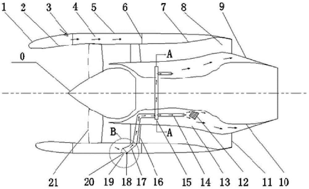
[0039] figure 1 It shows a structural schematic diagram of an aircraft engine that uses the cooling airflow of the fan compartment to ventilate and cool the core compartment. Such as figure 1 As shown, an aircraft engine generally includes a core compartment and a fan compartment, and various components 12 are provided in the core compartment. During the operation of the aircraft, especially during the flight, the fan compartment ...


PUM


Abstract

The invention provides a cooling method and device for an engine core module. According to the method, cooling airflow in a fan cabin is reutilized and introduced into the core module so as to cool the core module. In the ground test state, ambient airflow enters the fan cabin for ventilation cooling through an exhaust port of the fan cabin in a free convection mode and is discharged through an air inlet of the fan cabin finally. In other flying states, ambient airflow enters through the air inlet of the fan cabin under the ram action, is divided into a left stream and a right stream for ventilation cooling of the fan cabin, and then is introduced into the core module through an air guiding pipe under the differential pressure of the fan cabin and the core module to conduct ventilation cooling on the core module, and meanwhile, the ambient airflow can conduct directional concentrated cooling on the local high-temperature region in the cabin under the guiding of the air guiding pipe. In this way, ventilation cooling of the core module is achieved, the air entraining content of an external duct is reduced, entraining loss of the external duct is reduced, and reutilization of ventilation cooling airflow of the fan cabin is achieved.

Description

Technical field [0001] The invention relates to a flight engine, in particular to a cooling method and a cooling device for the core compartment of an aircraft engine. Background technique [0002] The engine core compartment contains the engine core engine, casing, and various engine accessories. When the engine is working, a large amount of heat is transferred to the core compartment through the casing. If the heat cannot be dissipated in time or quickly accumulates, the pipelines and accessories in the compartment will not work properly, and even cause a fire. The core compartment ventilation and cooling system can cool down on the one hand The various accessories mounted on the engine casing and the casing itself, on the other hand, can ensure the air circulation inside the cabin, thereby preventing the accumulation of flammable gases in the cabin and eliminating fire hazards. Therefore, the core compartment ventilation and cooling technology is of great significance to ensu...

Claims


Application Information

Patent Timeline
Patent Type & Authority Applications(China)
IPC IPC(8): F01P1/00B64D33/08
Inventor 陈俊邓阳张建东
Owner AECC COMML AIRCRAFT ENGINE CO LTD
Why Eureka
Try Eureka