Device and process for comprehensively treating BOG generated by LNG receiving station at initial stage of production

A technology of comprehensive processing and receiving station, applied in the field of BOG processing of LNG receiving station

Active Publication Date: 2015-09-30
CHINA NAT OFFSHORE OIL CORP +2
View PDF6 Cites 3 Cited by
  • Summary
  • Abstract
  • Description
  • Claims
  • Application Information

AI Technical Summary

Problems solved by technology

Traditional liquefaction still has problems such as the inability to deal with flash evaporation after liquefaction, the narrow range of liquefaction load adjustment, and the inconvenience of maintenance due to the large number of moving equipment.
The start-up of the traditional liquefaction cold box is particularly slow. The LNG storage tank is empty when unloading the ship for the first time (the liquefaction device cannot be started in advance for hot backup), and the unloading time is about 10 hours, while the traditional liquefaction cold box cannot be started within 10 hours. Therefore, it cannot effectively handle a large number of BOG generated by the first unloading

Method used


Image

  • Device and process for comprehensively treating BOG generated by LNG receiving station at initial stage of production

Examples


Embodiment 1

[0023] Use a liquefaction cell:

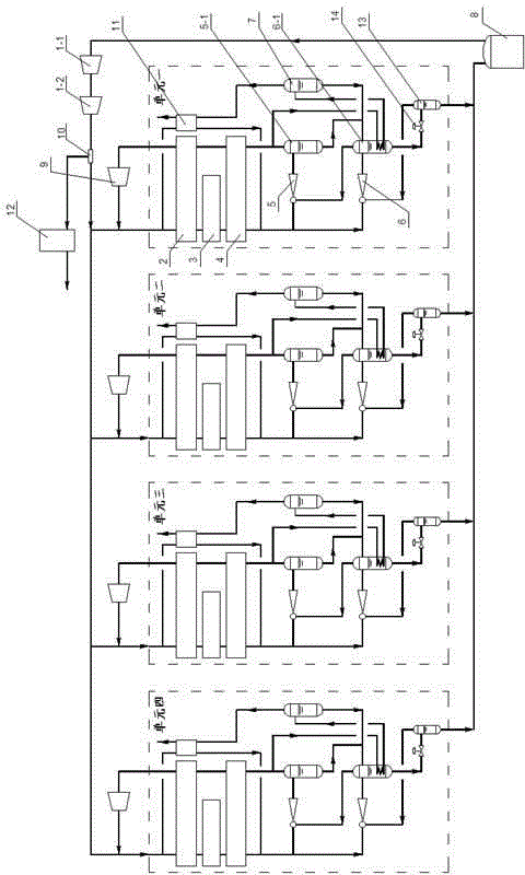
[0024] The comprehensive treatment device includes an LNG storage tank 8, a low-pressure BOG compressor 1-1, a high-pressure BOG compressor 1-2 and a CNG filling interface 10, the BOG gas phase outlet pipeline of the LNG storage tank 8 and the low-pressure BOG compressor 1-1. The inlet is connected, the outlet pipeline of the low-pressure BOG compressor 1-1 is connected with the inlet of the high-pressure BOG compressor 1-2, the outlet pipeline of the high-pressure BOG compressor 1-2 is connected with the inlet of the CNG filling interface 10, and the CNG filling interface 10 is connected The outlet pipeline is divided into two paths, one pipeline is connected to the CNG filling machine 12, and the other pipeline is connected to the inlet of the liquefaction unit, the gas phase outlet pipeline of the liquefaction unit is connected to the circulating BOG compressor 9, and the outlet pipeline of the circulating BOG compressor 9 is connected to th...

Embodiment 2

[0033] Use two liquefaction units set up in parallel:

[0034] The comprehensive treatment device includes an LNG storage tank 8, a low-pressure BOG compressor 1-1, a high-pressure BOG compressor 1-2 and a CNG filling interface 10, the BOG gas phase outlet pipeline of the LNG storage tank 8 and the low-pressure BOG compressor 1-1. The inlet is connected, the outlet pipeline of the low-pressure BOG compressor 1-1 is connected with the inlet of the high-pressure BOG compressor 1-2, the outlet pipeline of the high-pressure BOG compressor 1-2 is connected with the inlet of the CNG filling interface 10, and the CNG filling interface 10 is connected The outlet pipeline is divided into two paths, one pipeline is connected to the CNG filling machine 12, and the other pipeline is connected to the inlet of the liquefaction unit, the gas phase outlet pipeline of the liquefaction unit is connected to the circulating BOG compressor 9, and the outlet pipeline of the circulating BOG compresso...

Embodiment 3

[0043] Using four liquefaction units set up in parallel:

[0044] The comprehensive treatment device includes an LNG storage tank 8, a low-pressure BOG compressor 1-1, a high-pressure BOG compressor 1-2 and a CNG filling interface 10, the BOG gas phase outlet pipeline of the LNG storage tank 8 and the low-pressure BOG compressor 1-1. The inlet is connected, the outlet pipeline of the low-pressure BOG compressor 1-1 is connected with the inlet of the high-pressure BOG compressor 1-2, the outlet pipeline of the high-pressure BOG compressor 1-2 is connected with the inlet of the CNG filling interface 10, and the CNG filling interface 10 is connected The outlet pipeline is divided into two paths, one pipeline is connected to the CNG filling machine 12, and the other pipeline is connected to the inlet of the liquefaction unit, the gas phase outlet pipeline of the liquefaction unit is connected to the circulating BOG compressor 9, and the outlet pipeline of the circulating BOG compre...


PUM


Abstract

The invention discloses a device and a process for comprehensively treating BOG generated by an LNG receiving station at the initial stage of production and belongs to the technical field of BOG treatment of LNG receiving stations. The device for comprehensively treating the BOG comprises an LNG storage tank, a low-pressure BOG compressor, a high-pressure BOG compressor and a CNG filling opening, wherein a BOG gas phase outlet pipeline of the LNG storage is communicated with the inlet of the low-pressure BOG compressor; an outlet pipeline of the low-pressure BOG compressor is communicated with the inlet of the high-pressure BOG compressor; an outlet pipeline of the high-pressure BOG compressor is communicated with the inlet of the CNG filling opening; an outlet pipeline of the CNG filling opening is divided into two paths, one path of the pipeline is communicated with a CNG filling machine, and the other path of pipeline is communicated with the inlet of a liquefaction unit; a gas phase outlet pipeline of the liquefaction unit is communicated with a circulating BOG compressor; an outlet pipeline of the circulating BOG compressor is communicated with the inlet of the liquefaction unit; a liquid phase outlet pipeline of the liquefaction unit is communicated with the liquid phase inlet of the LNG storage tank. Compared with the prior art, the device has a CNG outer conveying function, is relatively flexible and reliable in BOG treatment, simple in equipment maintenance and convenient in operation.

Description

technical field [0001] The invention relates to the technical field of BOG processing at LNG receiving stations, in particular to a comprehensive processing device and process for BOG generated at LNG receiving stations at the initial stage of commissioning. Background technique [0002] LNG (Liquefied Natural Gas) is the abbreviation of liquefied natural gas. Due to its huge energy cleanliness advantages, LNG is currently being vigorously developed in China. Corresponding LNG receiving stations have sprung up like mushrooms after rain, and construction has started in Guangdong, Fujian, Zhejiang, Jiangsu and other places. [0003] After the completion of the LNG receiving station, there is often the actual situation that the construction of the pipeline network is relatively backward. Generally, it will lag behind the construction of the LNG receiving station by about one year, and some projects may take longer. The traditional process of processing BOG (Boil-off gas) in t...

Claims


Application Information

Patent Timeline
Patent Type & Authority Applications(China)
IPC IPC(8): F17C5/02F17C5/06F17C13/00
Inventor 仇德朋董洪茂徐国峰曲顺利郭雷杨同莲鹿晓斌朱艳艳张华伟
Owner CHINA NAT OFFSHORE OIL CORP
Why Eureka
Try Eureka