Heat pump type microchannel heat exchanger

A micro-channel heat exchanger and heat pump technology, applied in the field of air-conditioning heat exchangers and refrigeration and air-conditioning, can solve the problems of inability to achieve accurate positioning, end flanging and lodging, and different heights of fins, and achieve convenient installation and increased strength. , the effect of uniform spacing

Inactive Publication Date: 2015-09-30
ZHEJIANG DUNAN ARTIFICIAL ENVIRONMENT
View PDF6 Cites 5 Cited by
  • Summary
  • Abstract
  • Description
  • Claims
  • Application Information

AI Technical Summary

Problems solved by technology

However, the long sides of the two ends of the above-mentioned finned flat tube insertion holes are turned out separately, and there is a section of fins between the short sides of the two sides and the long sides of the two ends without flanging. During the assembly process of the heat exchanger, the flat tubes are inserted When finning, due to welding requirements, the gap between the flat tube and the fin needs to be kept small, so that there is friction between the flat tube and the fin during the process of inserting the flat tube into the fin, and at the same time, due to the finned flat tube The flanges on both sides of the insertion hole are disconnected from both ends, resulting in the deterioration of the strength of the disconnected part and the positioning flanges. The friction force during the assembly process of the flat tube tends to cause the end flanges to fall, while the two sides The fins will also bend and deform along the insertion direction of the flat tube due to friction, so that accurate positioning cannot be achieved, and the height of the fins will also vary, reducing the heat transfer performance

Method used


Image

  • Heat pump type microchannel heat exchanger
  • Heat pump type microchannel heat exchanger
  • Heat pump type microchannel heat exchanger

Examples


Embodiment 2

[0051] The technical solution of Embodiment 2 is to consider that when the heat exchanger is placed vertically, due to the small inclination angle of the two long sides of the flat tube, a slight inclination of the heat exchanger during initial installation or operation may cause the long side of the upper side of the flat tube to be caused. level, resulting in the retention of condensed water on the upper surface of the flat tube. When there is an included angle between the center line of the two short sides of the flat tube cross-section and the horizontal plane, the inclination of the long side of the flat tube is increased, thereby avoiding the above problems, and the condensed water on the flat tube can be discharged smoothly.

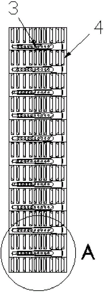
[0052] like Figure 12 and Figure 13 As shown, in Embodiment 3, both ends of the flat tube insertion hole 40 are provided with installation holes 401, the installation holes 401 are rectangular, and the flanges on both sides of the installation ...


PUM


Abstract

The invention discloses a heat pump type microchannel heat exchanger which comprises flat tubes and fins. A flat tube insertion hole is formed in each fin, the width dimension of each flat tube is H1, the width dimension H2 of each flat tube insertion hole is larger than the width dimension H1 of each flat tube, the flat tubes are clamped into the corresponding flat tube insertion holes and fixed in a welded mode, turned edges are arranged on each fin along the periphery of the corresponding flat tube insertion hole, an installation hole with the width larger than that of the corresponding flat tube is reserved at one end or at the two ends of each flat tube insertion hole. According to the technical scheme, the installation hole with the width larger than that of the corresponding flat tube is reserved at one end or at the two ends of each flat tube insertion hole to form a larger space or a cutting edge, and the space can be used for installing flat tube installation guide rails to fix the relative positions of the fins, so that dislocation of fins does not occur, and installation of the flat tubes is convenient.

Description

technical field [0001] The invention relates to the field of refrigeration and air conditioning, in particular to the field of air conditioning heat exchangers. Background technique [0002] figure 1 and figure 2 It is the structure of the prior art air conditioner heat exchanger, including a first header 1, a second header 2, a flat tube 3 with micro-channel holes and fins 4, and the first header 1 is provided with an inlet pipe 10 , the second header 2 is provided with an outlet pipe 20, the fins are provided with a flat tube insertion hole, the flat tube is inserted into the flat tube insertion hole and fixed by welding. [0003] In order to strengthen the welding strength, the fins are provided with flanges along the periphery of the flat tube insertion hole. Due to the small width of the flat tubes in the microchannel heat exchanger, although the peripheral flanging of the insertion holes of the flat tubes on the fins can strengthen the welding strength, the flangin...

Claims


Application Information

Patent Timeline
IPC IPC(8): F25B39/00F28F1/26
CPCF25B39/00F28F1/26F28F2260/02
Inventor 汪峰钟建法陈舟苗
Owner ZHEJIANG DUNAN ARTIFICIAL ENVIRONMENT
Why Eureka
Try Eureka