
Electrochemical luminescence bioanalysis flow cell based on magnetic beads

A bioluminescent and electrochemical technology, applied in the direction of material electrochemical variables, can solve the problems of large dead volume, space occupation, and large consumption of the pool body, and achieve the effects of improving detection sensitivity, detection speed, and service life

Active Publication Date: 2015-09-30
SUZHOU UNIV
View PDF5 Cites 6 Cited by
  • Summary
  • Abstract
  • Description
  • Claims
  • Application Information

AI Technical Summary

Problems solved by technology

[0005] 1. The three electrodes must be inserted into the cell, occupying the space in the cell and limiting the development of the detection system to miniaturization. In addition, a large amount of ECL reagents are consumed in actual detection;
[0006] 2. Manual sample addition and repeated disassembly of the cell body lead to the inability to keep the relative positions of the three electrodes fixed, which affects the reproducibility of ECL test results;
[0008] 4. The pool body has a large dead volume, etc.
[0009] These will lead to the reduction of the performance of the electrochemiluminescent cell and its analytical precision and sensitivity.

Method used


Image

  • Electrochemical luminescence bioanalysis flow cell based on magnetic beads
  • Electrochemical luminescence bioanalysis flow cell based on magnetic beads
  • Electrochemical luminescence bioanalysis flow cell based on magnetic beads

Examples


Embodiment Construction

[0032] The specific implementation manners of the present invention will be further described in detail below in conjunction with the accompanying drawings and embodiments. The following examples are used to illustrate the present invention, but are not intended to limit the scope of the present invention.

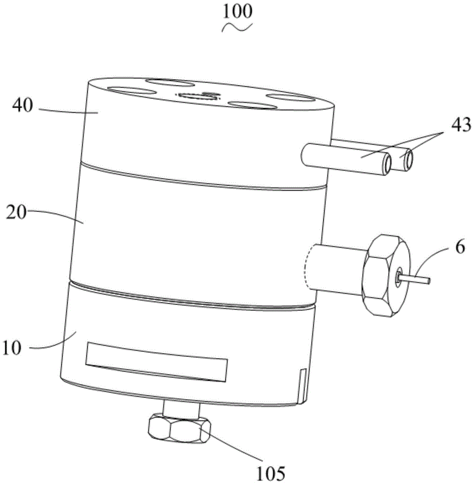
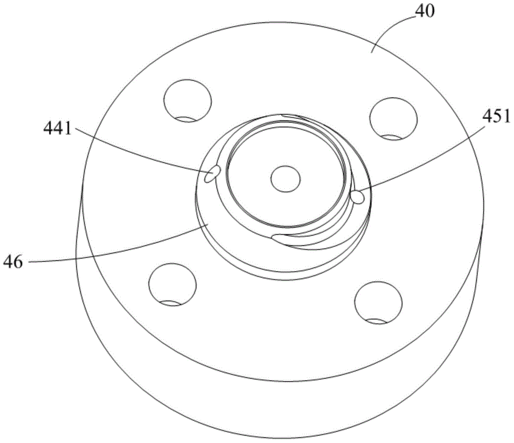
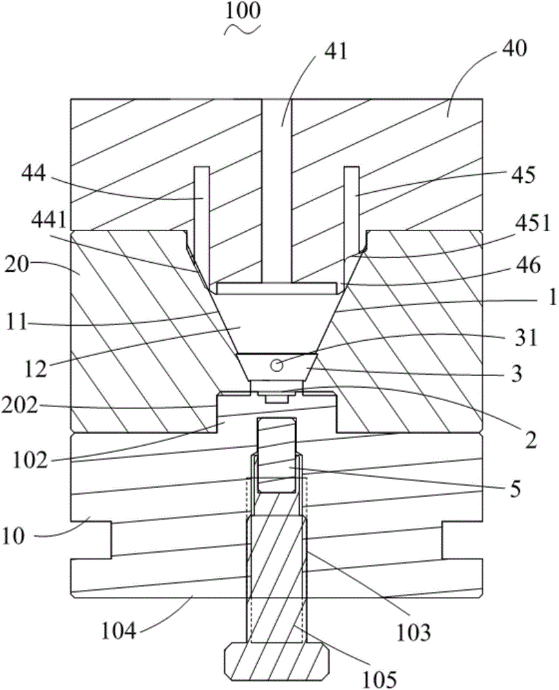
[0033] see Figure 1 to Figure 4 A flow cell 100 for electrochemiluminescent bioanalysis based on magnetic beads described in Embodiment 1 of the present invention includes a funnel 1 with a top opening (not numbered) and a bottom opening (not numbered) arranged oppositely, and is arranged on the funnel 1 the seal 102 at the bottom to close the bottom opening of the funnel 1, the working electrode 2 arranged on the upper surface of the seal 102, the counter electrode 3 embedded in the funnel 1, and the top opening of the funnel 1 closed The cover 40 , the magnet 5 and the reference electrode 6 that can move relative to the working electrode 2 . The funnel 1 includes an i...


PUM


Abstract

The invention relates to an electrochemical luminescence bioanalysis flow cell based on magnetic beads. The electrochemical luminescence bioanalysis flow cell comprises a hopper, a sealing piece, a work electrode, a counter electrode, a cover and a magnet, wherein the hopper is provided with a top opening and a bottom opening which are oppositely formed, the sealing piece is arranged at the bottom of the hopper to close the bottom opening of the hopper, the work electrode is arranged on the upper surface of the sealing piece, the counter electrode is embedded in the hopper, the cover closes the top opening of the hopper, and the magnet can move relative to the work electrode. The counter electrode is embedded in the hopper in the axial direction of the hopper in a surrounding mode. The hopper comprises an inner wall and a hopper cavity defined by the inner wall. The cover is provided with a light channel penetrating through the cover. The light channel is communicated with the hopper cavity. The light channel is provided with an optical lens. The cover is provided with a liquid inlet and outlet channel. The hopper cavity is communicated with the outer portion through the liquid inlet and outlet channel. The electrochemical luminescence bioanalysis flow cell based on the magnetic beads is overall miniaturized, the number of ECL reaction reagents for bioanalysis is relatively small, in other words, the consumed ECL reaction reagents are relatively few, no dead volume exists, liquid is rapidly replaced, and fast analysis is achieved.

Description

technical field [0001] The invention relates to an electrochemiluminescent biological analysis flow cell based on magnetic beads, which belongs to detection equipment. Background technique [0002] In the past few decades, great progress has been made in the research of electrochemiluminescence (ECL) bioanalysis based on magnetic beads. The corresponding detection equipment mainly includes three parts: electrochemiluminescence cell, photoelectric converter and detector. The ECL cell is the core part of the ECL research system. Both signal acquisition and detection for ECL analysis are dependent on the performance and design of the cell. However, because there are still relatively few commercialized ECL cells, the degree of specialization is low, and many performances are not perfect, most researchers have to design and manufacture ECL cells by themselves according to their own experimental requirements. [0003] At present, for the structural design of the ECL cell, a thre...

Claims


Application Information

Patent Timeline
IPC IPC(8): G01N27/28
Inventor 谢洪平魏同洪葛芝莉
Owner SUZHOU UNIV
Learn More