Fuel battery flow field plate

A fuel cell and flow field plate technology, which is applied to fuel cells, fuel cell parts, circuits, etc., can solve the problems of reducing the efficiency of electrochemical reactions, reactants cannot reach the reaction interface, and do not take into account, so as to improve the electrochemical performance. The effect of reaction efficiency, simple structure and reliable performance

Active Publication Date: 2015-09-30
NANJING UNIV OF AERONAUTICS & ASTRONAUTICS
View PDF4 Cites 8 Cited by
  • Summary
  • Abstract
  • Description
  • Claims
  • Application Information

AI Technical Summary

Problems solved by technology

The purpose of this flow field plate is to discharge water in time, but it does not consider how to make the CO in the reaction 2 Bubbles are discharged in time to avoid CO 2 Bubbles block in the flow field channel and occupy the active position of the catalyst on the methanol electrode, which prevents the reactants from reaching the reaction interface and reduces the efficiency of the electrochemical reaction

Method used


Image

  • Fuel battery flow field plate
  • Fuel battery flow field plate
  • Fuel battery flow field plate

Examples


Embodiment 1

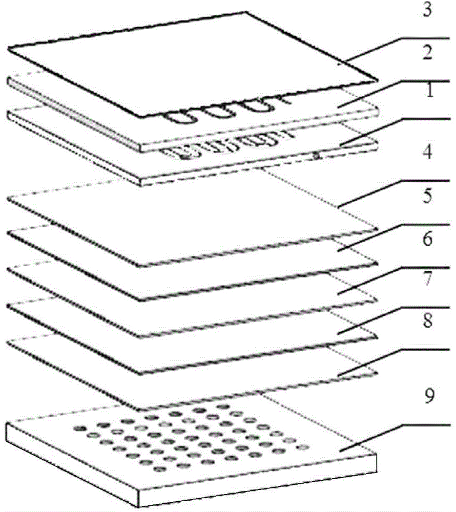
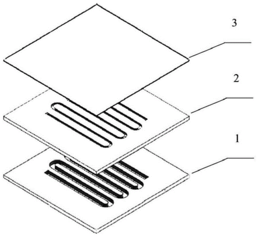
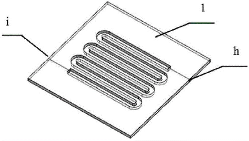
[0019] A fuel cell flow field plate, such as figure 1 As shown, it consists of the bottom flow field plate 1, the middle flow field plate 2 and the top flow field plate 3, and the layers are bonded with sealant; the middle part of the bottom flow field plate 1 and the middle flow field plate 2 is provided with a corresponding Corresponding S-shaped through groove. Such as figure 2 As shown, an inlet h and an outlet i are respectively provided on two opposite sides of the bottom flow field plate 1, and the inlet h and the outlet i communicate with the through groove. Such as image 3 As shown, the cross-sectional shape of the through groove of the bottom flow field plate 1 is rectangular, and the cross-sectional shape of the through groove of the middle layer flow field plate 2 is trapezoidal, and the size of the bottom of the trapezoid is equal to the size of the transverse side of the rectangle; but in practical applications, the through groove The cross-sectional shape i...


PUM


Abstract

The invention provide a fuel battery flow field plate which comprises a bottom flow field plate, a middle flow field plate and a top flow field plate, wherein two adjacent flow field plates are bonded by a sealant; S-shaped through grooves which are corresponding with each other in shape and size are formed in the middles of the bottom flow field plate and the middle flow field plate; the sections of the through grooves of the bottom flow field plate and the middle flow field plate are different in shape; the bottom flow field plate is made of a hydrophilic material, the middle flow field plate is made of a hydrophobic material; and the top flow field plate is made of an air-liquid separation film. The fuel battery flow field plate disclosed by the invention is simple in structure, stable to work, and reliable in performance; and the air-liquid splitting-phase conveying of fuel can be realized, so that CO2 bubbles in reaction can be discharged in real time, and the electrochemical reaction efficiency can be improved.

Description

technical field [0001] The invention belongs to the technical field of fuel cells, and in particular relates to a fuel cell flow field plate. Background technique [0002] A fuel cell is a clean energy source that directly converts chemical energy into electrical energy. It mainly consists of membrane electrode assembly (anode diffusion layer, anode catalyst layer, proton exchange membrane, cathode catalyst layer and cathode diffusion layer) and flow field plates (anode flow field plate and cathode flow field plate). The flow field plate is attached with a metal layer on the side facing the membrane electrode assembly or directly uses metal materials to collect current, and at the same time, the flow field plate is processed with micro channels for uniform distribution of reactants. [0003] Direct Methanol Fuel Cell (DMFC) has a wide range of applications in the fields of portable electronic products and micro-electromechanical systems due to its high efficiency, envir...

Claims


Application Information

Patent Timeline
Patent Type & Authority Applications(China)
IPC IPC(8): H01M8/02
CPCH01M8/026H01M8/0263H01M8/0265Y02E60/50
Inventor 李苗苗朱如鹏耿骏
Owner NANJING UNIV OF AERONAUTICS & ASTRONAUTICS
Why Eureka
Try Eureka