Quasi frequency peak current control method applied to BUCK circuit

A technology of peak current control and inductive current, which is applied in the direction of control/regulation system, electrical components, and adjustment of electrical variables, etc., which can solve the problems of affecting the transient response characteristics of switching power supply, unstable switching of compensation slope, and increasing the amount of calculation of the control system, etc. , to achieve the effect of improving dynamic response performance, easy digital realization, and small amount of calculation

Inactive Publication Date: 2015-09-30
SOUTHWEST JIAOTONG UNIV
View PDF6 Cites 12 Cited by
  • Summary
  • Abstract
  • Description
  • Claims
  • Application Information

AI Technical Summary

Problems solved by technology

However, if the same constant compensation slope is used to compensate all duty cycle ranges, this often results in a large excess of slope compensation, which seriously affects the transient response characteristics of the switching power supply.
Especially in the control state, when the output current is zero, excessive compensation may also cause the peak current mode control to change to the voltage mode control, which is not desired
The method based on slope compensation requires that different compensation slopes can be generated under different duty cycles, which will increase the amount of calculation of the control system and cause some unstable problems of compensation slope switching

Method used


Image

  • Quasi frequency peak current control method applied to BUCK circuit
  • Quasi frequency peak current control method applied to BUCK circuit
  • Quasi frequency peak current control method applied to BUCK circuit

Examples


Embodiment Construction

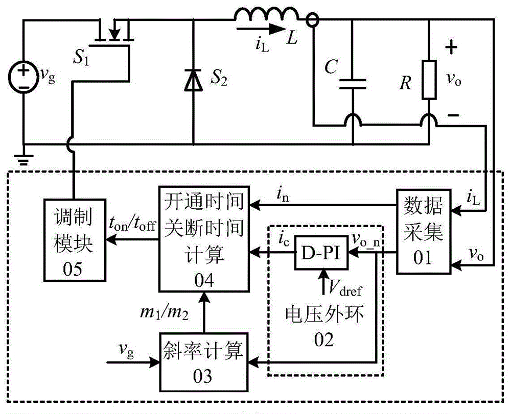
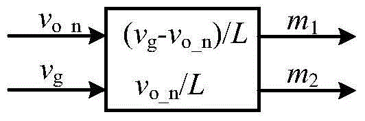
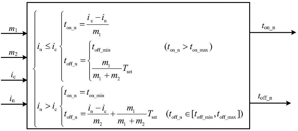
[0030] figure 1 A system block diagram of the quasi-fixed frequency peak current control method of the BUCK circuit is shown. The whole system includes: data acquisition 01 acquisition output voltage v o and the inductor current i L , the output voltage passes through the outer loop voltage PI controller 02 to obtain the peak current given value i c . Also, depending on the output voltage v o and the stored input voltage v g Calculate the inductance current rise rate m through slope calculation 03 1 and inductor current drop rate m 2 . Combined with the peak current given value i c and the inductor current change rate m 1 and m 2 Calculate the switch conduction time t by calculating the turn-on and turn-off time 04 on and switch off time t off . Finally according to the switch conduction time t on and switch off time t off The control signal of the converter is obtained through the modulation module 05 to complete the control of the converter. The specific cont...


PUM


Abstract

The invention discloses a quasi frequency peak current control method applied to a BUCK circuit. Output voltage and inductive current signals are acquired, switch on time and off time are obtained by a quasi frequency control method, switch control signals are generated, and a BUCK converter is controlled. A control system comprises a data acquisition module 01, an outer ring voltage PI (proportional-integral) controller module 02, a slope calculation module 03, an on and off time calculation module 04 and a modulation module 05. The slope of inductive current is calculated when a switch is turned on and off, the on time and the off time are calculated, the switch control signals are acquired by the modulation module, the BUCK converter is controlled, and steady and transient performances of the BUCK converter are improved by the quasi frequency control method.

Description

technical field [0001] The invention relates to the field of design and manufacture of control systems for BUCK circuits (including forward type, flyback type and half-bridge and full-bridge type BUCK converters) in the field of switching power supplies. Background technique [0002] DC-DC converters are not widely used, especially in military, industrial, household, medical and coal mines. The traditional DC-DC conversion power supply often adopts linear power supply technology, but this structure causes problems such as low overall efficiency, poor performance, and large volume and weight of the power supply. Therefore, the DC power supply tends to adopt switching power supply technology, which makes the DC power supply high efficiency, better performance, small size and light weight. With the rapid development of power electronics technology, the rapid development and innovation of switching power supply technology has been promoted, and the application fields have becom...

Claims


Application Information

Patent Timeline
Patent Type & Authority Applications(China)
IPC IPC(8): H02M3/156
Inventor 宋文胜侯聂马俊鹏冯晓云葛兴来王青元
Owner SOUTHWEST JIAOTONG UNIV
Why Eureka
Try Eureka