Digital tube display LED shadowless lamp circuit with double dimming function

A LED shadowless lamp and digital display technology, applied in the direction of electric lamp circuit layout, light source, electric light source, etc., can solve the problems of unintuitive display gear, poor high and low temperature resistance, complex control circuit, etc., and achieve strong anti-interference ability and high cost , the effect of high power consumption

Inactive Publication Date: 2015-09-30
NANTONG MEDICAL DEVICES
View PDF8 Cites 2 Cited by
  • Summary
  • Abstract
  • Description
  • Claims
  • Application Information

AI Technical Summary

Problems solved by technology

[0002] At present, the brightness control of LED shadowless lamps generally adopts a single digital PWM pulse dimming control, which has shortcomings
For example: a. There is gear adjustment, each gear corresponds to a fixed brightness, poor selectivity, not as uniform as stepless dimming control; b. This control method has a certain frequency, although the human eye cannot detect it, but For the eyes, strobe is unavoidable. General shadowless lamps use LED lamp posts, or LCD display working status or gear position
Disadvantages: The LED lamp post type display gear is not intuitive, while the LCD screen type has disadvantages such as complex control circuit, poor high and low temperature resistance, high cost, and high power consumption; the common connection circuit form of the digital tube light-emitting circuit is to use several resistors , to achieve separate current limiting for each segment of digital tubes, the disadvantage is that more resistors are used; the brightness of LED shadowless lamp beads is started as a non-transitional start, and the current transiently changes from 0 to the maximum, which will have a certain impact on its life

Method used


Image

  • Digital tube display LED shadowless lamp circuit with double dimming function
  • Digital tube display LED shadowless lamp circuit with double dimming function

Examples


Embodiment approach

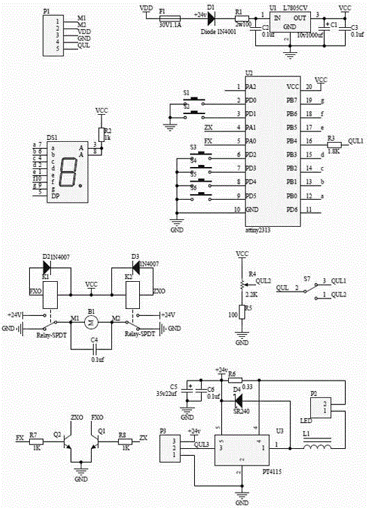
[0020] 1. After the 24V DC power supply is short-circuited and over-current protected by F1, it is sent to U1 through the anti-reverse connection diode D1, the step-down resistor R1, and the interference-removing capacitor C2, and the 5V control power supply is obtained after filtering by C1 and C3;

[0021] 2. S7 is the dimming mode selection switch. When 2 and 3 are connected, it is digital PWM gear dimming, otherwise it is DC stepless dimming. R4 and R5 are DC stepless dimming circuits, which can be changed by changing the resistance of R4. Control the voltage to control the brightness of the shadowless lamp;

[0022] 3. R2 and DS1 are status display circuits, and all LED segments share a current-limiting resistor, which is controlled by the program to make its luminous brightness uniform;

[0023] 4. D2, D3, B1, C4, K1, and K2 are the forward and reverse control circuits of the motor. For example, the micro-processing chip U2 receives the command to adjust the size of the ...


PUM


Abstract

The invention relates to a digital tube display LED shadowless lamp circuit with a double dimming function. The digital tube display LED shadowless lamp comprises a power source input device and a power source processing device used for processing the power source input device which is connected with an LED driving device, a relay driving device and a micro processing chip, and the relay driving device is connected with the micro processing chip. The digital tube display LED shadowless lamp circuit has the advantages that the circuit is high in stability, free of stroboflash, harmless for eyes and long in service life and has the double dimming function, and starting current impact strength of LED lamp beads is reduced.

Description

technical field [0001] The invention relates to a shadowless lamp circuit, in particular to a nixie tube display LED shadowless lamp circuit with dual dimming functions. Background technique [0002] At present, the brightness control of LED shadowless lamps generally adopts a single digital PWM pulse dimming control, which has shortcomings. For example: a. There are gear adjustments, and each gear corresponds to a fixed brightness. The selectivity is poor, and it is not as uniform as stepless dimming control; b. This control method has a certain frequency, although the human eye cannot perceive it, but For the eyes, strobe is unavoidable. General shadowless lamps use LED lamp posts, or LCD display working status or gear position. Disadvantages: The LED lamp post type display gear is not intuitive, while the LCD screen type has disadvantages such as complex control circuit, poor high and low temperature resistance, high cost, and high power consumption; the common connectio...

Claims


Application Information

Patent Timeline
Patent Type & Authority Applications(China)
IPC IPC(8): H05B37/02
Inventor 孙晓胜潘卫国
Owner NANTONG MEDICAL DEVICES
Why Eureka
Try Eureka