Resonance damping for audio transducer systems

An audio transducer and audio signal technology, applied in the direction of electrostatic transducer microphone, transducer shell/cabinet/stand, sensor, etc., can solve the problem of undesired output signal and so on

Active Publication Date: 2015-09-30
NOKIA TECHNOLOGLES OY
View PDF6 Cites 4 Cited by
  • Summary
  • Abstract
  • Description
  • Claims
  • Application Information

AI Technical Summary

Problems solved by technology

In these cases, such a high-Q resonance may produce an undesired output signal at the resonant fre

Method used


Image

  • Resonance damping for audio transducer systems
  • Resonance damping for audio transducer systems
  • Resonance damping for audio transducer systems

Examples


Embodiment Construction

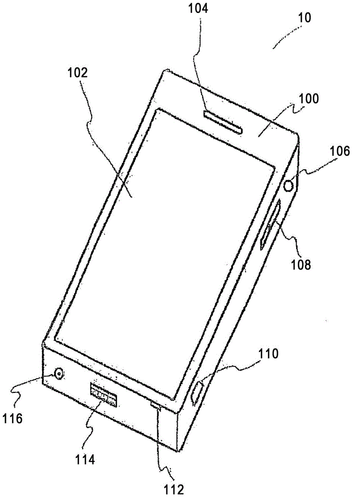
[0060] Suitable means and possible mechanisms are described in further detail below for illustrating example systems including known solutions for sound generating systems. Such as figure 1 The device shown is in the form of a mobile phone. It should be understood, however, that embodiments of the present application may be practiced within any device or apparatus that includes a transducer, which may be a speaker module. For example, in other embodiments the apparatus may be an electronic device such as a music player or a wireless communication system such as a mobile phone, smart phone, PDA, computer, music player, video player or adapted to output an audio signal any other type of equipment.

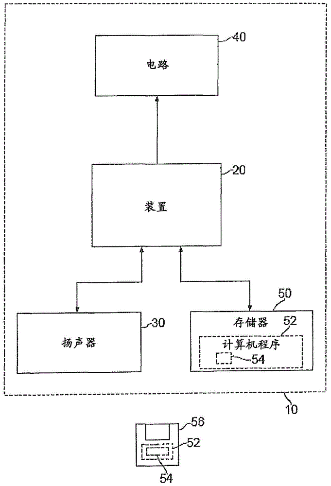
[0061] Audio signals, such as music signals, may be suitably processed using digital signal processing (DSP) as described herein together with audio amplifiers preceding the speaker modules. The speaker module is suitably integrated inside an electronic device comprising one or mo...


PUM

PropertyMeasurementUnit
Diameteraaaaaaaaaa

Abstract

An apparatus (10) comprising: an audio transducer (201) configured to at least one of: generate sound upon receiving an audio signal provided by the apparatus (10); and convert sound into an audio signal to be processed by the apparatus (10); a housing component (301) comprising one or more sound apertures (303) configured to allow the transmission of sound through the one or more sound apertures (303); and an acoustic cavity (203) inside the apparatus (10) being acoustically coupled to the audio transducer (201) using the one or more sound apertures (303) wherein the one or more sound apertures (303) are configured to provide an acoustic damping.

Description

technical field [0001] The present invention relates generally to the fields of acoustics and audio transducer integration, and more particularly to the use of microapertures positioned between an audio transducer and an acoustic cavity to provide acoustic damping for resonance. Background technique [0002] Mobile devices often include audio components (eg speakers, microphones) integrated within the device. Such integration of audio components requires consideration of the mechanical and acoustic properties of these components which may sometimes conflict with desired acoustic properties. One of these considerations concerns the acoustic resonance when the transducer is integrated inside the mobile device. [0003] Speaker integration for hands-free functionality should produce sufficient sound pressure levels, extended bandwidth (especially low frequency response), low levels of distortion, etc. However, such loudspeaker integration inside the device may have disadvanta...

Claims


Application Information

Patent Timeline
IPC IPC(8): H04R19/04H04R1/04H04R19/00
CPCH04R2499/11H04R1/2888H04R1/2819H04R1/20H04R1/2842
Inventor 施胜荣
Owner NOKIA TECHNOLOGLES OY
Why Eureka
Try Eureka