
Guiding catheter

A catheter and steel tube technology, applied in the direction of catheters, etc., can solve the problems of increasing the difficulty and cost of the patient's lumen tissue damage, prolonging the radiation time of doctors and patients, and inability to adapt.

Active Publication Date: 2015-10-07
APT MEDICAL HUNAN INC
View PDF6 Cites 30 Cited by
  • Summary
  • Abstract
  • Description
  • Claims
  • Application Information

AI Technical Summary

Problems solved by technology

[0003] However, in clinical use, even if various distal pre-shaped guiding catheters are developed according to specific human physiological anatomical structures, they cannot fully adapt to individual physiological anatomical structures.
For this reason, during the operation, the doctor usually withdraws the catheter and chooses another pre-shaped guide catheter again. In the process of replacing the guide catheter, it will undoubtedly increase the difficulty of the doctor's operation and the patient's burden. The cost and the chance of damage to the patient's luminal tissue will even prolong the radiation time of doctors and patients

Method used


Image

  • Guiding catheter
  • Guiding catheter
  • Guiding catheter

Examples


Embodiment 1

[0064] The reinforcing layer 17 of the bending section 3 and the reinforcing layer 17 of the main body 4 are all provided with two backguy cavities 19, such as Figure 10 As shown, the two cable chambers 19 are distributed axially symmetrically. The handle includes a handle sleeve 21, a handle dial 22, two stay wire fixing devices 23, a damping plate 24, a handle upper cover 26, an embedded cover 27, a damping ring 28 and a handle lower cover 29, wherein: the handle dial 22 is sleeved on the handle On the boss of loam cake 26, handle dial 22 has two regulators and all can make handle dial 22 rotate along the center of boss by stirring any regulator; In the annular groove, the damping ring 28 is embedded in the annular groove; the damping disc 24 abuts against the handle dial 22 and the damping disc 24 fits with the boss of the handle upper cover 26, and the fastener runs through the damping disc 24 and the protrusion of the handle upper cover 26. The platform is fixedly conne...

Embodiment 2

[0076] In this embodiment, the bending section 3 and the main body 4 are provided with a cable cavity 19, such as Figure 11 As shown, the handle includes a housing 32, a screw 31 and a guide block 35, a screw rod 36 and a steel pipe 33 that are all arranged inside the housing 32, wherein:

[0077] The threaded end of the screw rod 36 is connected with the screw device 31 through threaded cooperation, and the fixed end of the screw rod 36 is fixedly connected with the guide block 35. Specifically, the screw rod 36 is a moving part of the handle, and its threaded end has an external thread. It can cooperate with the internal thread on the screw 31, and the pitch of the thread that the two cooperate with is relatively large, and can produce relative movement quickly. The rear end of the screw rod 36 is a flat structure, embedded in the guide block 35, which can effectively prevent the rotation of the screw rod 36; The front end of the steel pipe 33 is fixedly connected with the...


PUM


Abstract

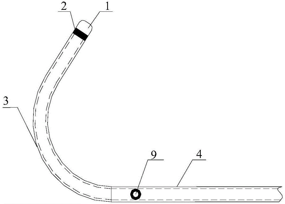
The invention discloses a guiding catheter. The guiding catheter comprises a head end, a tail end and a main body part used for being connected with the head end and the tail end. The guiding catheter is provided with a catheter cavity and further comprises a bending adjustment section and a bending adjustment assembly. The first end of the bending adjustment section is connected with the head end, and the second end of the bending adjustment section is connected with the end, facing the head end of the guiding catheter, of the main body part of the guiding catheter. A central cavity of the bending adjustment section is communicated with the catheter cavity. The bending adjustment assembly comprises a handle. One end of a pulling string penetrates through the main body part and the bending adjustment section and is connected with the first end of the bending adjustment section. The other end of the pulling string is led out through the tail end of the guiding catheter and is connected with the handle. The length of the portion, placed in the main body part, of the pulling string and the length of the portion, placed in the bending adjustment section, of the pulling string can be adjusted through the handle. Due to the fact that the bending angle of the bending adjustment section is changed directly through the pulling string, the angle of the head end of the guiding catheter can be adjusted according to the physiological structure of a patient, the head end of the guiding catheter is made to stretch into a lesion position, and the applicability of the guiding catheter can be improved.

Description

technical field [0001] The invention relates to the technical field of medical instruments, in particular to a guiding catheter. Background technique [0002] With the development of interventional medical technology, interventional diagnosis and treatment catheters, especially guiding catheters, have been widely used in human interventional diagnosis and treatment operations. Generally speaking, due to differences in human anatomical structures, doctors often need to use interventional diagnosis and treatment catheters of various shapes, structures, and sizes to establish a channel between the diseased part of the patient's body and the outside of the patient's body. [0003] However, in clinical use, even if various distal pre-shaped guiding catheters designed according to specific human physiological anatomical structures are developed, they cannot fully adapt to individual physiological anatomical structures. For this reason, during the operation, the doctor usually wit...

Claims


Application Information

Patent Timeline
Patent Type & Authority Applications(China)
IPC IPC(8): A61M25/00A61M25/01
Inventor 成正辉刘新潮杨林
Owner APT MEDICAL HUNAN INC
Learn More