Method for flue gas denitration through partial oxidation, absorption and recycle
A flue gas and oxidation tower technology, which is applied in separation methods, chemical instruments and methods, and dispersed particle separation, can solve the problems of oxidant consumption and high operating costs, reduce consumption, reduce operating costs, and realize denitrification and resource utilization Effect
- Summary
- Abstract
- Description
- Claims
- Application Information
AI Technical Summary
Problems solved by technology
Method used
Image

Examples
Embodiment 1
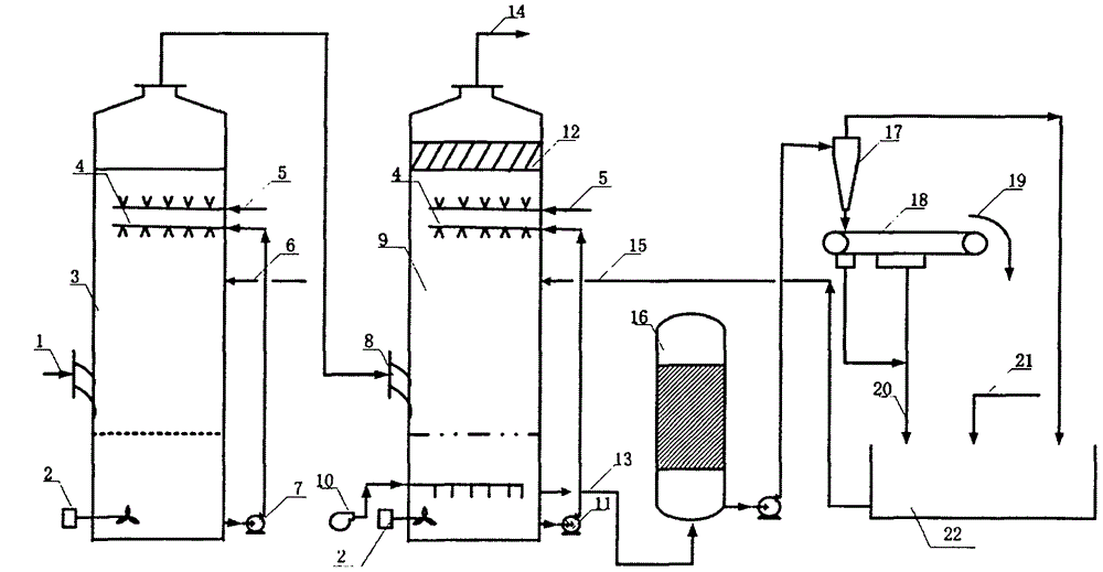
[0029] The flue gas denitrification test is carried out in the device shown in the attached figure. The oxidation tower is a glass spray tower with a diameter of 100mm and a height of 100cm. The gas-liquid two-phase countercurrent flow is 30m. 3 / h, the oxidant is hydrogen peroxide, the concentration is 0.1mol / L, the liquid spray volume is 100L / h, the temperature is 40°C, the pH value is 5, and the NO inlet concentration is 1200mg / m 3 , the flue gas residence time is 3 seconds, the denitrification tower is a glass spray tower with a diameter of 100mm and a height of 100cm, the mass concentration of sodium hydroxide is 6%, the liquid spray volume is 150L / h, the temperature is 40°C, and the pH value is 9 , the NO inlet and outlet concentration in the flue gas was measured by the KM940 flue gas analyzer of the British Kane company, and the NO outlet concentration was 75 mg / m after the operation was stable. 3 , the removal rate was 93.8%, and sodium nitrate solid was obtained.
Embodiment 2
[0031] The test device is the same as that of Example 1, the gas-liquid two-phase counterflow, and the flue gas flow rate is 30m 3 / h, the oxidant is potassium permanganate, the concentration is 0.15mol / L, the liquid spray volume is 50L / h, the temperature is 40°C, the pH value is 6, and the NO inlet concentration is 1200mg / m 3 , the flue gas residence time is 3 seconds, the mass concentration of the lye in the denitrification tower is 6% sodium hydroxide, the liquid spray volume is 150L / h, the temperature is 40°C, the pH value is 9, and the concentration of NO in the flue gas is Measured by the KM940 flue gas analyzer of the British Kane company, the NO outlet concentration after the operation is stable is 56 mg / m 3 , the removal rate was 95.3%, and sodium nitrate solid was obtained.
Embodiment 3
[0033] The test device is the same as that in Example 1, the gas-liquid two-phase counterflow, and the flue gas flow rate is 40m 3 / h, the oxidant is sodium hypochlorite, the concentration is 0.15mol / L, the liquid spray volume is 60L / h, the temperature is 40°C, the pH value is 6, and the NO inlet concentration is 1100mg / m 3 , the flue gas residence time is 2.5 seconds, the lye in the denitrification tower is ammonium carbonate with a mass concentration of 8%, the liquid spray volume is 100L / h, the temperature is 40°C, and the pH value is 9. Measured by the KM940 flue gas analyzer of British Kane Company, the outlet concentration of NO is 65 mg / m after the operation is stable 3 , the removal rate was 94.1%, and sodium nitrate solid was obtained.
PUM
| Property | Measurement | Unit |
|---|---|---|
| Diameter | aaaaa | aaaaa |
Abstract
Description
Claims
Application Information
 - R&D Engineer
- R&D Manager
- IP Professional
- Industry Leading Data Capabilities
- Powerful AI technology
- Patent DNA Extraction
Browse by: Latest US Patents, China's latest patents, Technical Efficacy Thesaurus, Application Domain, Technology Topic.
© 2024 PatSnap. All rights reserved.Legal|Privacy policy|Modern Slavery Act Transparency Statement|Sitemap