Method for calibrating full-automatic visual inspection machines for products

A calibration method and visual inspection machine technology, which is applied in the calibration field of material sorting machines, can solve problems such as poor coordination of moving distance, inability to effectively pick up products, and machine failure to work normally, so as to achieve the effect of improving work efficiency

Inactive Publication Date: 2015-10-07
RES INST OF ZHEJIANG UNIV TAIZHOU
View PDF6 Cites 3 Cited by
  • Summary
  • Abstract
  • Description
  • Claims
  • Application Information

AI Technical Summary

Problems solved by technology

However, in the actual use process, due to mechanical displacement and computer reset, it is easy to cause a large gap between the original stored data in the computer and the actual data, resulting in that the rotation angle of the turntable and the moving

Method used


Image

  • Method for calibrating full-automatic visual inspection machines for products
  • Method for calibrating full-automatic visual inspection machines for products

Examples


Embodiment 1

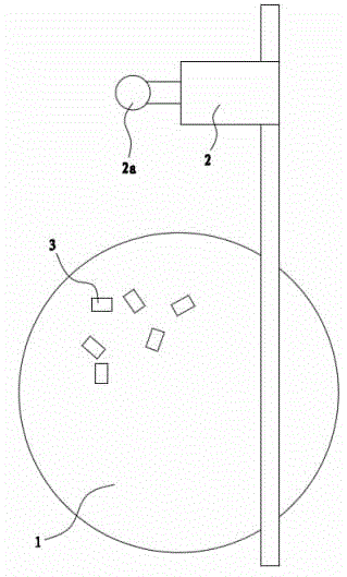
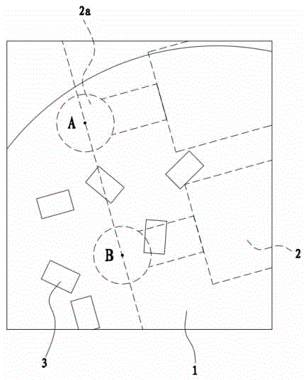
[0036] Such as figure 1 As shown, the product automatic visual inspection machine includes a turntable 1 and a linear motor 2 . During work, product 3 is placed on the turntable 1. In this visual inspection machine, there may be some inclinations in the setting angle of the imaging system, as in figure 2 As shown in , the path of the linear motor 2 in the field of view of the camera has a certain angle of inclination.

[0037] During the use of the visual inspection machine, there are uncertain factors, such as the offset of the imaging system, the offset of the turntable 1 and the linear motor 2, the reset of computer data, and the mechanical wear in the visual inspection machine, etc. 2. The product 3 cannot be picked up or the effect of picking up the product 3 is not good, so the visual inspection machine needs to be calibrated.

[0038] This calibration method includes the calibration of the path of the linear motor and the calibration of the center of the turntable. ...

Embodiment 2

[0061] This calibration method includes the calibration of the path of the linear motor and the calibration of the center of the turntable.

[0062] The linear motor 2 path calibration includes the following steps:

[0063] A1. Manipulate the linear motor 2 to move from the origin to the motor point 1 according to the preset displacement b1, and the motor point 1 is located in the field of view of the camera; the motor point 1 is as figure 2 Point A shown in ; the position of motor point 1 is located at 1 / 3 of the travel path of linear motor 2 in the camera field of view;

[0064] B1. Place a product 3 directly under the suction head 2a of the linear motor 2;

[0065] C1. Determine the coordinate p1 of the center point of the product 3 in step B1 in the field of view of the camera; specifically, use an image processing algorithm to obtain the center position of the product 3 . An imaging mechanism is set in the visual inspection machine to facilitate the imaging of the prod...


PUM


Abstract

The invention discloses a method for calibrating full-automatic visual inspection machines for products, and belongs to the technical field of methods for calibrating machines. By the aid of the method, the problem of poor product picking effects of existing visual inspection machines can be solved. The method includes calibrating paths of linear motors and circle centers of turntables, to be more specific, A1, shifting the linear motors to first motor points according to preset displacement b1; B1, arranging a product below each sucker; C1, determining coordinates p1 of the center points of the products in visual fields of cameras; D1, shifting the linear motors to second motor points according to preset displacement b2; E1, placing a product below each sucker; F1, determining coordinates p2 of the center points of the products in the visual fields of the cameras; G1, respectively computing coordinates of origins of the linear motors, amplification factors of the cameras and the paths of the linear motors and inputting data to computers. The method has the advantage that the products can be effectively picked by the linear motors after the full-automatic visual inspection machines are calibrated by the aid of the method.

Description

technical field [0001] The invention belongs to the technical field of machine calibration and relates to a calibration method for a material sorting machine. Background technique [0002] Quartz wafers used in industry are cut into pieces from quartz rods, and then processed through a series of processes. Due to the special conditions of use, quartz wafers must meet strict quality requirements, meet specific frequencies, and have damage of a certain size on the surface: such as scratches (including over-edge scratches and internal scratches), cracks, chipping, chipping, shape Defects such as irregularities and surface dirt will directly affect the performance of the chip. After a single wafer is molded, it needs to undergo frequency screening and then undergo surface inspection before it can be used to make crystal resonators. However, the current wafer surface inspection process in the domestic crystal industry relies entirely on manual visual inspection, which has low e...

Claims


Application Information

Patent Timeline
IPC IPC(8): B07C5/34B07C99/00
Inventor 陈浙泊林斌张鑫
Owner RES INST OF ZHEJIANG UNIV TAIZHOU
Why Eureka
Try Eureka