Adjustable self-centering tool false shaft

A tooling dummy shaft and self-centering technology, which is applied to workpiece clamping devices, metal processing, manufacturing tools, etc., can solve the problems of low utilization rate and increased production cost, and achieve high utilization rate, high positioning accuracy and convenient operation Effect

Active Publication Date: 2015-10-07
NANTONG COSCO HEAVY IND
View PDF9 Cites 0 Cited by
  • Summary
  • Abstract
  • Description
  • Claims
  • Application Information

AI Technical Summary

Problems solved by technology

Especially for products that are not mass-produced, the utilization rate of a large number of dummy shafts of different specifications is not only very low, but also greatly increases the production cost

Method used


Image

  • Adjustable self-centering tool false shaft
  • Adjustable self-centering tool false shaft
  • Adjustable self-centering tool false shaft

Examples


Embodiment Construction

[0013] The following structural drawings describe in detail the adjustable self-centering frock dummy shaft of the present invention.

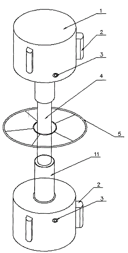
[0014] combine Figures 1 to 3 It can be seen that an adjustable self-centering tooling false shaft includes a connecting rod 4, a rotating handle 5, and a cylindrical support 1. The rotating handle 5 is arranged in the middle of the connecting rod 4, and the cylindrical support 1 is arranged symmetrically. at both ends of connecting rod 4.

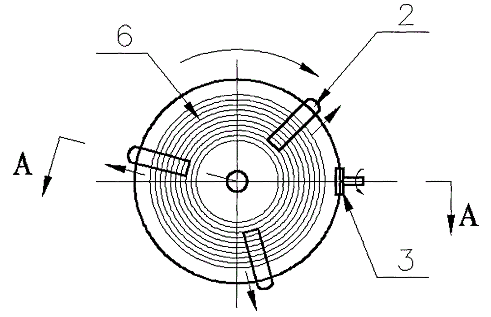
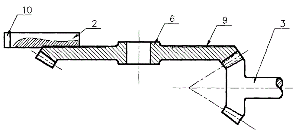
[0015] The cylindrical support 1 includes three strip braces 2 , and the strip braces 2 are evenly distributed at 120 degrees on the side wall of the cylindrical support 1 . The supporting surface 10 of the strut 2 is a cylindrical surface.

[0016] Described cylinder bearing 1 also comprises adjusting nut 3, rotating disk 6, and described rotating disk 6 is arranged on the inside of cylinder bearing 1, and the back side of described rotating disk 6 is provided with plane threaded knot 9, and the back s...


PUM


Abstract

The invention discloses an adjustable self-centering tool false shaft which comprises a connection rod and supports. The supports are symmetrically arranged at the two ends of the connection rod and are cylinders. Each support comprises supporting rods, an adjusting nut, a rotary plate and a shaft sleeve, wherein the supporting rods are evenly distributed on the side wall of the support, and the rotary plate is disposed in the support; a planar thread structure is arranged on the back side of the rotary plate, and the back side of the rotary plate is parallel to the end face of the support; the adjusting nut is engaged with the rotary plate through a conical gear, and the adjusting nut is arranged on the side wall of the support; the supporting rods are in threaded connection with the back side of the rotary plate, and the shaft sleeve is arranged on the end face of the support. Threads are disposed at the two ends of the connection rod, the threads at the two ends of the connection rod are opposite structures, and the connection rod is in threaded connection with the shaft sleeve. The adjustable self-centering tool false shaft is high in adaptability and utilization rate, large in adjustment range, high in positioning precision and convenient to operate, and the manufacturing cost of the false shaft is greatly lowered.

Description

technical field [0001] The invention relates to a tooling dummy shaft, in particular to a self-centering tooling dummy shaft. Background technique [0002] In mechanical assembly, many links will involve assembly coaxiality. In order to ensure the coaxiality requirements, in many cases, the assembly of mechanical parts, the assembly and welding of ear plates in the steel structure industry will use dummy shafts as tooling, which not only ensures the assembly accuracy, but also improves the assembly efficiency. However, the size of the existing dummy shaft is fixed after processing. The diameter of the dummy shaft depends on the size of the shaft hole, and the length of the dummy shaft depends on the distance between the lugs. If there are many specifications of the shaft holes, the distance between the lugs will vary greatly. Then it is necessary to manufacture false shafts of many specifications. Especially for products that are not mass-produced, the utilization rate of ...

Claims


Application Information

Patent Timeline
Patent Type & Authority Applications(China)
IPC IPC(8): B23P19/00B25B11/00
Inventor 陈建春葛新波甄春艳葛双喜陈鑫祎
Owner NANTONG COSCO HEAVY IND
Why Eureka
Try Eureka